Hello world 😀
I have an amp simulated and as real device, but I've some problems to simulate it's open loop gain. Is there anything out as info that can you recommend to read ?
Next problem is the compensation of the amp....At the moment there's only the capacitor across B-C of the VAS transistor...but there I must put >300pF in to get the amp stable at any load (in the real world). What's about a second order pole in the feedback ? In the simulation that works fine...but in real world ?????
Thanks.....
Attachments
Attachments
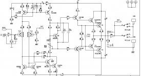
You have a supply rail filter D4 + R37 (10 Ohm)
I would rather put this before the VAS Constant current source.
So I should move them to the right of T7.
Current sources benefit from clean, constant voltage supply.
And this is what the filter D4 + R37 helps to give. su
I would rather put this before the VAS Constant current source.
So I should move them to the right of T7.
Current sources benefit from clean, constant voltage supply.
And this is what the filter D4 + R37 helps to give. su
strange , this is almost the same as my "AX" which runs stable down to 22pF ?? 😕
edit , GET RID of the Darlington drivers !!! (tip 102/107) most likely they are the problem.
OS
edit , GET RID of the Darlington drivers !!! (tip 102/107) most likely they are the problem.
OS
Last edited:
Ok... I've found something about testing OL gain in simulation (making the feedback R from output to some MOhms and replacing the feedback resistor to ground by 10F (!) ).
So I've Open Loop gain... the compensation in the simulation works fine (just where I want it) and I also get best results in simulation... but bad results in real world :-(
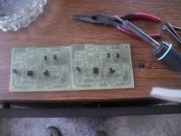
One prototype (breadboard) is performing well... the PCB type seems to be instable.... mhhhh... can the emitter resistors make an amplifier unstable ? There where other types on the breadboard than on the PCB....
So I've Open Loop gain... the compensation in the simulation works fine (just where I want it) and I also get best results in simulation... but bad results in real world :-(
One prototype (breadboard) is performing well... the PCB type seems to be instable.... mhhhh... can the emitter resistors make an amplifier unstable ? There where other types on the breadboard than on the PCB....
strange , this is almost the same as my "AX" which runs stable down to 22pF ?? 😕
edit , GET RID of the Darlington drivers !!! (tip 102/107) most likely they are the problem.
OS
Why not darlingtons ? capacity too high ? They make unbelievable current gain 😎
Why not darlingtons ? capacity too high ? They make unbelievable current gain 😎
Oscillation city... standard MJE15032/33 drivers will give 2k hfe in a standard EF2 output stage and will allow the "blameless" to run on a single 33/47pF Cdom rock solid. I don't lie , i'm building my 10th pair of your amp "ax" below.
OS
Attachments
It has a darlington VAS and this type is always difficult to tame, you need good layout, lot of compensation and some luck.Because of this I never use darlington VAS in amplifiers and if you look at commercial amplifiers you will see that it's also very seldom used.
i've always done the OLG measurement " the hard way".... feed a 1uv signal in with no feedback, and tweak the dc offset of the simulated signal source until the output comes off the rails. once i get a useable output signal, i measure the amplitude and do the gain calculation. it helps to terminate the inverting input with a resistor the same value as what you use for Rser of the signal source to balance the input bias currents. it takes a lot of test runs of the sim just to get the output offset anywhere near normal and i'm sure parameter stepping would save some time here. there are also other ways to measure the OLG that use some clever sim tricks. these can be found in the file section of the LTSpice yahoo group.
T17 is not a good choice either...
Use a BC546 for as much as +-55V PS.
For higher voltage, stick to 2SC2240.
use the BD139 as T12 if the supply is no more than +-35V...
For higher PS voltage, try 2SC3423.
Use a BC546 for as much as +-55V PS.
For higher voltage, stick to 2SC2240.
use the BD139 as T12 if the supply is no more than +-35V...
For higher PS voltage, try 2SC3423.
Whats about 2SA1930 / 2SC5171 as driver instead of TIP10x ?
It s just another world...
From the 1976 VW Golf 1 to a current Audi TT.....
I dont know if you have told your voltage supply.
I will assume clear below +/-40 Volt
Input stage.
Think it looks very good. The idea is absolutely right.
I am unsure how much current you have here.
You use a GREEN LED + MJE350 for current source.
My guess is above 2.5 mA per input transistor.
Now, almost nobody uses green LED.
Because RED LED + transistor gives more constant current. A better current source.
If we assume < 40V and 5 mA we can use BC560C in CCS (constant current source)
Because less than 200 mWatt is okay for a 500 mW device.
(I would say we should avoid to get above 250 mWatt for 500 mWatt devices.
That is, for small signal transistors do not use more than max 50% of the max power rating)
I be back with some thoughts on VAS, if you want.
But Ostripper has already given some good advices.
He is very clever and knows much. More than me 😀
Supply is about +- 40V (up to 45V if idle...)
There are about 6mA for DiffPair and approx 11mA for VAS......
--> that makes ~ 0.5W idle and 1W peak for VAS transistor..
I will give 2SA1930 / 2SC5171 a chance 🙂
There are about 6mA for DiffPair and approx 11mA for VAS......
--> that makes ~ 0.5W idle and 1W peak for VAS transistor..
I will give 2SA1930 / 2SC5171 a chance 🙂
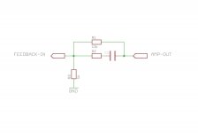
and see pic
If I interpret your schematic correctly it seems feedback is taken from the wrong side of the output L//R network.
Furthermore, the VAS may be destroyed by clipping in its current configuration. You might want to fix that. 😉 A collector resistor for T17 or an antisaturation diode across the miller cap could solve this issue.
I am unsure how much current you have here.
You use a GREEN LED + MJE350 for current source.
My guess is above 2.5 mA per input transistor.
Now, almost nobody uses green LED.
Because RED LED + transistor gives more constant current. A better current source.
You can use green led as current source , the only difference is 2.2v Vf instead of of 1.65-1.7V for red LED. A 150R Re for the red led might be a 180-200Re for the "greenie" , no biggie!!😀 Do the math . (or let the sim do it for you)
I use all 4 colors (blue/green/red/yellow) , even for CCS's. 🙂
OS
- Status
- Not open for further replies.
- Home
- Amplifiers
- Solid State
- OpenLoop Gain and compensation