Is that resistor across pins 1 and 5? Is it worth doing?
You're not bored of it already?! 😉
Is that resistor across pins 1 and 5? Is it worth doing?
You mean pin 4 or pin 8?
For an NE5532 or LM4562, it should be pin 4, but since the OPA1612 has a rail-rail output stage, I put the resistor across pins 1 and 8 (main amplifier output and V+). This is to make most of the current go through the NPN and less through the PNP.
My observation is that it helps. To be honest, I first connected the resistors accidentally to the V- supply and noticed the sound getting worse!
Next step should be to clean up the V+ supply. I already improved it a bit by using Panasonic FM instead of stock on the inside 1000uF caps C402/403 (on the outside caps C76/77, this is not possible, because the caps would hit the casing). Obviously, having all that supply ripple and noise fed to the output stage is not so great.
I'd be interested in the results after kicking out the LM7805/7815/7915. Even using two mass-produced LM317/337 in tracking-preregulator configuration should give a massive improvement.
--
Greetz,
MatchASM
Yes, sorry 1 & 8! My bad 😀
Trips : Don't you mean "with" - Your bad

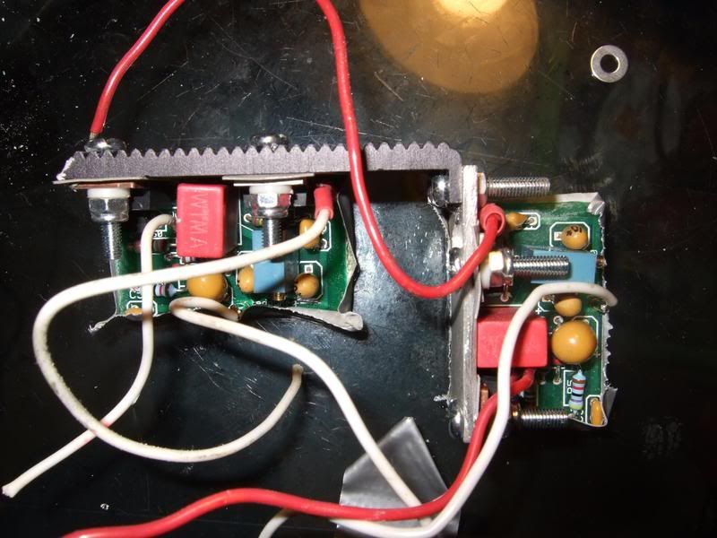
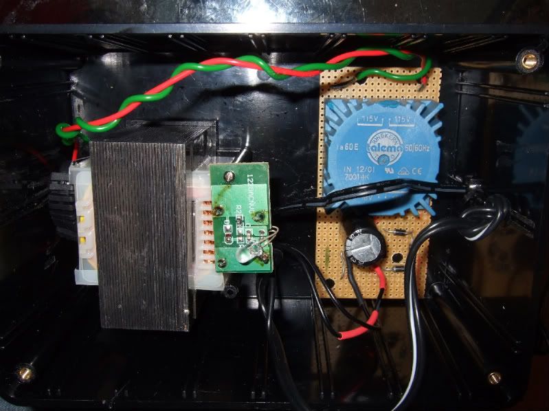
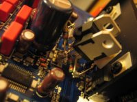
The +15/-15v Teddyregs are now fitted. I don't think i'd ever want to do that again, because they were a right pain in the bum to fit. I had to cut a piece of a aluminium and bolt it onto the side of the existing heatsink (I used some Arctic silver 5 thermal paste in the joint)
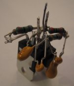
Here's a picture of the Teddyregs attached to the bodged heatsink:
Here's a picture of the Teddyregs attached to the bodged heatsink:
Here's a pic of the regs in the Dacmagic:
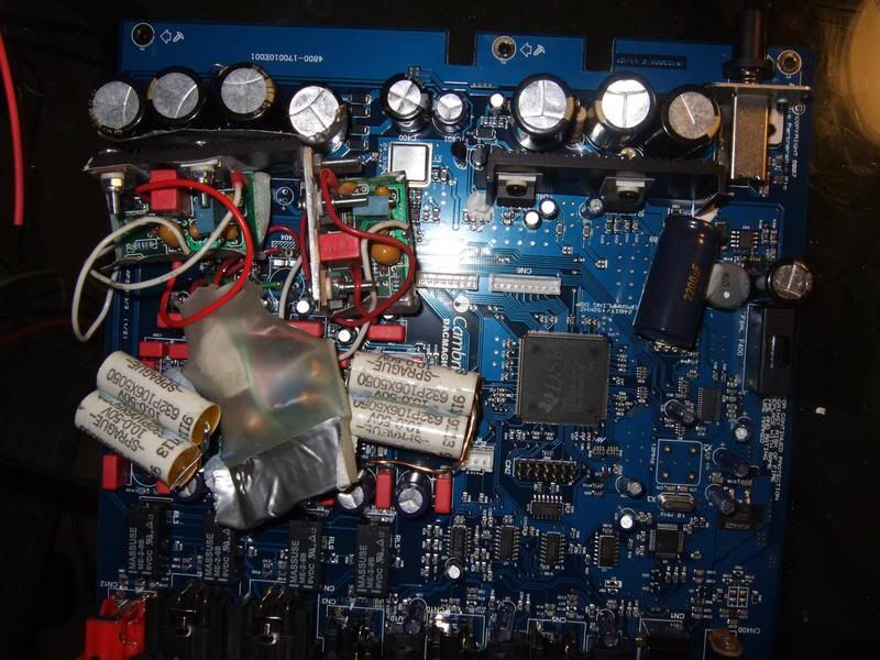
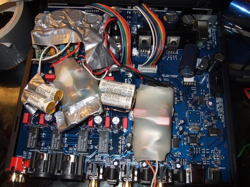
And this one is with just the one Teddyreg feeding the dacs:
And this one is with just the one Teddyreg feeding the dacs:

yes, ferrite bead FB5 should be removed in order to supply crystal with clean power. Don't forget to remove FB4 in order to supply U14 with clean power. U14 is distributing MCLK to DSP and DAC chips 😀
power supply
Hey.
I think that I've found, what there is to be found about Dac magic in Denmark. and we are a couple of guys discussing the Dac Magic and it posibillitys at danish hifi homepages. so i would very much like to follow your guy's work here 😀
just to start somewhere easy, I've just about to order lme4972/lm4562 and a bunch of cap's. But as mentioned, several times. The power section needs some serious work aswell.
Is it correctly understood, that the powersupply simply can be built seperatly in a external box, and then just solder wires into the DM, after the original power supply has been disabled?
And which are the most important ones to imporve? all of the dc's. or only +/-15v, 5v and 3,3V???
Thank you. Great work done here 😎
I'm not sure I understand the question. Are you planning to use your own mains transformer? If you are not, and simply substituting the regulator ICs, the answer would be yes. If you are using your own mains transformer, I'm not sure if there is a constraint on the startup sequence of the rails.Is it correctly understood, that the powersupply simply can be built seperatly in a external box, and then just solder wires into the DM, after the original power supply has been disabled?
I think the 5V DAC supply is probably most important, followed by either the +/-15V or the 5V clock supply.And which are the most important ones to imporve? all of the dc's. or only +/-15v, 5v and 3,3V???
Enjoy the soldering!
--
Greetz,
MatchASM
Puttering about the Dac Magic
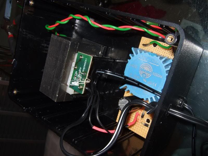
Actually I want to keep the DM as original as possible. I might throw the EI core away and use a toroid instead.
I was told that if I simply replace the regulator inside the DM, it would not make any difference. Since It is the construction of the power supply and not the regulator, that is the problem.
So i might stick with swapping capacitors and op-amps.
I also heard that a single channel op-amp sounds better than a dual op-amp. So I'm looking for a so called brown-dog converter. This should allow me to install two single channel op-amps, in each dual foot-print in the DM. But I'm still in the research fase 😱)
Thanks
I'm not sure I understand the question. Are you planning to use your own mains transformer? If you are not, and simply substituting the regulator ICs, the answer would be yes. If you are using your own mains transformer, I'm not sure if there is a constraint on the startup sequence of the rails.
I think the 5V DAC supply is probably most important, followed by either the +/-15V or the 5V clock supply.
Enjoy the soldering!
--
Greetz,
MatchASM
Actually I want to keep the DM as original as possible. I might throw the EI core away and use a toroid instead.
I was told that if I simply replace the regulator inside the DM, it would not make any difference. Since It is the construction of the power supply and not the regulator, that is the problem.
So i might stick with swapping capacitors and op-amps.
I also heard that a single channel op-amp sounds better than a dual op-amp. So I'm looking for a so called brown-dog converter. This should allow me to install two single channel op-amps, in each dual foot-print in the DM. But I'm still in the research fase 😱)
Thanks
More Pictures
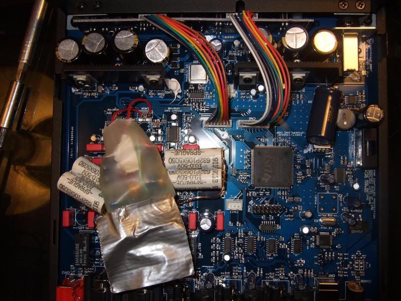
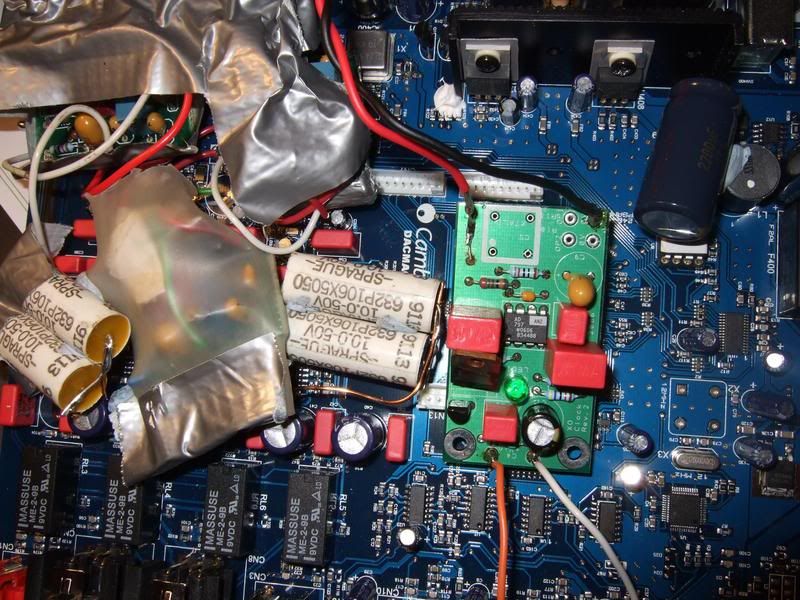
LM317s in pretracking configuration feeding the DACs, as on page 20 of National's LM317 datasheet (variable resistor fixed at 360 Ohms to give 5V output, ADJ pin of the output reg decoupled by 10u tantalum + 100n ceramic). They should be easier to fit than the TeddyReg and still give >100dB PSRR.
Also, I now put 20k resistors across pins 6 and 8 of the output (OP275 turned OPA1612) op-amps to give the coupling cap some DC bias. This will prevent the oxides from degrading and should give a considerable lifetime improvement. As an added bonus, the new bias setting should draw some current from the NE5532s, biasing also those little bastards more into class A 🙂
--
Greetz,
MatchASM
Attachments

I2S input
Does anyone know if it is possible to feed an I2S input directly into the DacMagic. I am considering hooking it up to a QA550 and all the reports on this device indicate that I2S is the way to go
Does anyone know if it is possible to feed an I2S input directly into the DacMagic. I am considering hooking it up to a QA550 and all the reports on this device indicate that I2S is the way to go
hi, is it possible to directly replaced the stock diode in dacmagic with MUR860?
and, i think the stock wallwart adapter does not perform that good..where can i find a good toroid/transformer for replacing this adapter? i can only find dual secondary in rsonline, or is it okay to use dual secondary?
nb: what does the "massuse me-2-9b" do? *the black rectangular things near C1, C2, C40, & C41
Last edited:
Stock diodes are S1D. They can be replaced with schottky diodes 10MQ100N
does changing the diode significantly alter the sound quality? i haven't checked the internal component nor have the long screwdriver to open the dacmagic up, if the stock diodes are already decent i wouldn't bother to change them..
wait, isn't the diode the to-220 case style thing, attached to the heatsink near the power supply caps?
Last edited:
wait, isn't the diode the to-220 case style thing, attached to the heatsink near the power supply caps?
no. those are (on the dac ic side) LM7815 and LM7915 and on the dsp side LM1117 and LM317. There are thirteen S1D type diodes in different places. I guess they can be replaced by MUR860, but you will be replacing SMD by TO220. Listen to stormsonic; he's a smart guy.
--
Greetz,
MatchASM
no. those are (on the dac ic side) LM7815 and LM7915 and on the dsp side LM1117 and LM317. There are thirteen S1D type diodes in different places. I guess they can be replaced by MUR860, but you will be replacing SMD by TO220. Listen to stormsonic; he's a smart guy.
--
Greetz,
MatchASM
in that case, i will skip diode replacement..smd soldering is too much of a hassle
what about the wallwart adapter, what transformer/toroid will do good to replace the stock adapter? so far i'm considering this dual secondary toroid: Nuvotem | Transformers | Transformers | Toroid Transformers | Toroidal 230Vac Primary 15VA to 1000VA |0030P1-2-012
idjoel2000 said:what about the wallwart adapter, what transformer/toroid will do good to replace the stock adapter? so far i'm considering this dual secondary toroid: Nuvotem | Transformers | Transformers | Toroid Transformers | Toroidal 230Vac Primary 15VA to 1000VA |0030P1-2-012
a lot of people are using THIS
- Home
- Source & Line
- Digital Line Level
- Opening the new DacMagic????