Had an interesting experience with replacing the digital power caps (excl. C87,C89 which are on Panasonic FC) to Oscon SP, especially C426,C431,C435.
Oscon SP's on C426/C431 had negative effect to sound experienced in high freq definition and stage separation. LM1117T spec requires lowest ESR at 0.3ohm, so SP Oscon's ESR at 0.06ohm should be the reason. So I went back to the original lytics for C426,C431,C435 which restored the sound to its original clarity.
Noticed ZLH caps ESR is also < 0.6ohm so which caps did you change to their ZLH equivalent ?
hi I used these: Farnell Export
Basically for fit more than anything else. Just ordered nichihon Muse ES bipolar for decoupling and output ,hope they are good😛
@evan12
I use Nichicon Muse ES for output. And they work fine. But I'm not sure how much I gained by this. I think that upgrading the power supply, is even more important.
Right know I'm "designing" a power supply, that will power both, main power, 5 volt, and my clock OSC.
I'm using a 40VA toroid trafo. It has 2 * 12Vac out. One 12Vac goes to the normal input. the second output will be bridge rectified. That should give me around 12*√2=17Vdc to work with. My clock OSC, accepts between 9-24Vdc, and has it's own little powersupply onboard, so that should be fine, with just a nice big cap to remove the rippel. It only draws max 20mA.
to make the 5Vdc and bypass the noisy DC-DC converter (Mc34063 (U12)). I'm thinking of removing R107, since I'm not using USB. Then I'll remove either L1 or L2. This will totally leave the MC34063, for easy reversal of this small operation, and at the same time give me some nice places to solder my new 5Vdc power onto the board.
to make the 5Vdc from the 17Vdc. I talked with some guys, telling me, that the 17Vdc comming from a rectifier, is only the peak-voltage. And NOT the correct voltage, when calculating the input voltage for a 7805. The explenation I got. Was that when you put on some load, the 17Vdc "rippel". Will decrase to maybe around 14V. furthermore, the bridge rectifier will pull 1,4Volts. Since there are two diode that each has a voltage drop across them, at 0,7V.
For the 7805 to regulate proberly. The datasheet says that it needs at least 2-3V of greater voltage at the input. So around 7-8 Volts - at least.
So I better make som real life test's. thought of using a power resistor that can handle 3-5W. Then I could reduce the 14V to maybe 9V. And then use the 7805.
Peeew. gonna be fun, to hear how much this will help, on the overall sound 😀
Also. I'm curious. Does it help to change coupling-caps like fx. C320 and C271, when I already use a Dexa regulator for this (U404) ??
Last edited:
@evan12
I use Nichicon Muse ES for output. And they work fine. But I'm not sure how much I gained by this. I think that upgrading the power supply, is even more important.
Right know I'm "designing" a power supply, that will power both, main power, 5 volt, and my clock OSC.
I'm using a 40VA toroid trafo. It has 2 * 12Vac out. One 12Vac goes to the normal input. the second output will be bridge rectified. That should give me around 12*√2=17Vdc to work with. My clock OSC, accepts between 9-24Vdc, and has it's own little powersupply onboard, so that should be fine, with just a nice big cap to remove the rippel. It only draws max 20mA.
to make the 5Vdc and bypass the noisy DC-DC converter (Mc34063 (U12)). I'm thinking of removing R107, since I'm not using USB. Then I'll remove either L1 or L2. This will totally leave the MC34063, for easy reversal of this small operation, and at the same time give me some nice places to solder my new 5Vdc power onto the board.
to make the 5Vdc from the 17Vdc. I talked with some guys, telling me, that the 17Vdc comming from a rectifier, is only the peak-voltage. And NOT the correct voltage, when calculating the input voltage for a 7805. The explenation I got. Was that when you put on some load, the 17Vdc "rippel". Will decrase to maybe around 14V. furthermore, the bridge rectifier will pull 1,4Volts. Since there are two diode that each has a voltage drop across them, at 0,7V.
For the 7805 to regulate proberly. The datasheet says that it needs at least 2-3V of greater voltage at the input. So around 7-8 Volts - at least.
So I better make som real life test's. thought of using a power resistor that can handle 3-5W. Then I could reduce the 14V to maybe 9V. And then use the 7805.
Peeew. gonna be fun, to hear how much this will help, on the overall sound 😀
Also. I'm curious. Does it help to change coupling-caps like fx. C320 and C271, when I already use a Dexa regulator for this (U404) ??
Sounds good , i havent changed those caps yet , i am going to change them with Muse ES type as those are the only ones i could find. I changed to dexa in the 79xx and 78xx positions and 7805 i put belleson regulators. Listening now and it sounds fantastic. Before these mods the dacmagic was not very magical but now its amazing. I am also using it with firstone audio Bravo with its power supply, makes a difference to the good.
@evan12
Right know I'm "designing" a power supply, that will power both, main power, 5 volt, and my clock OSC.
All PCB components, that is both Digital & Analog, share the same GND copper line which complicates matters if you try to isolate Clock, Analog, Digital - paid my lesson with a blown fuse.
Re: (Mc34063 (U12)), I believe it was a design decision to address current draw and power dissipation. C88 gives a switching freq of ~27khz which I think by raising around 87Khz should improve the overall current ripple performance. Power dissipation is a concern that I try to work around it.
Also a Load cap with low ESR (OsCon SVPC) would do a good work cleaning most the noise
See here: http://edc.sanyo.com/pdf/e_oscon/E_oscon_appli.pdf
ON Semi does an improved drop-pin replacement with higher switching speed and power dissipation.
*UPDATE*
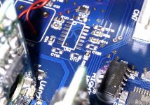
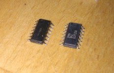
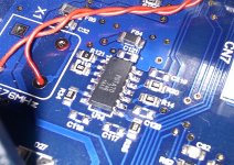
Have further worked on the clock chain and decided to replace the 74HVC14 with a higher speed / ultra low noise equivalent from Potato Semi ...
PO74G04 specs here: http://www.potatosemi.com/potatosemiweb/datasheet/PO74G04A.pdf
The mod also requires the removal of the C121 bypass cap as it affects IC noise performance.
The sound improvement is immediately noticeable especially in microdynamics/sound detail, soundstage and definition. I would definitely say PO74G04A makes the Crystek Oscillator with its -150db noise level, shine!!
re: clock PSU GND isolation, I gave up on the idea to use the digital isolator as this would definitely kill the clock quality between Crystek + PO74G04A.
PS: btw, my first SMD mod 🙂
Attachments
** CORRECTION **
The bypass cap *IS* required for the IC's internal noise cancellation logic. I got confused with the another clock buffer IC.
The mod also requires the removal of the C121 bypass cap as it affects IC noise performance.
The bypass cap *IS* required for the IC's internal noise cancellation logic. I got confused with the another clock buffer IC.
@Gvelim
Nice! 😀
My plan to remove R107. Did not work. Maybe the Unreg2 is needed somewhere. I tried giving it 5Vdc across C89. After removing L2. But now it wont start. helps a little, when i turn up the 5Vdc supply. So I better measure if the +5Vdc_DIG is 5Vdc. hmmmm. this could be tricky 😕
Nice! 😀
My plan to remove R107. Did not work. Maybe the Unreg2 is needed somewhere. I tried giving it 5Vdc across C89. After removing L2. But now it wont start. helps a little, when i turn up the 5Vdc supply. So I better measure if the +5Vdc_DIG is 5Vdc. hmmmm. this could be tricky 😕
My plan to remove R107. Did not work. Maybe the Unreg2 is needed somewhere. I tried giving it 5Vdc across C89. After removing L2. But now it wont start. helps a little, when i turn up the 5Vdc supply. So I better measure if the +5Vdc_DIG is 5Vdc. hmmmm. this could be tricky 😕
How much current your 5V supply can provide ? The MC36064 handles 1.2-1.5A peak current hence your PSU should be able to match this.
just connect everything back and when DAC is in use measure the voltage drop across R107. Then use V/R to calculate the current so you get an idea.
From the schematic I infer MC36064 implementation meets current requirements for DIG PSU around 1-1.2 amps.
PS: Some more impressions on PO74G04
http://amiexp.blogspot.com/2011/08/dsix-with-po74g04a.html
Last edited:
Thanks for advice, but I allready unsoldered the R107 😱
Problem solved. I'm using a large powersupply, with digital meters, to show both voltage and current drawn. And I just used a voltmeter to check the output. and it showed that it only gave 4,8 volts when showing 5v in the build in meter. so I simply adjusted it. and know it has been playing perfectly for the last 45 minutes 😀
The current drawn, is 0,38Amps. And my power supply can deliver around 2amps into 12Volts, so I was pretty sure, that the problem was not this 😉
it also seems that, it is rather important to turn the power on in the correct order. And right know I'm having two different linear PSU's. one for clock, and the other one for 5Vdc-digital.
Most definitely an improvement to bypass that MC34063 !! Sound is just better, in several ways. I'm not perfectly sure yet. But soundstage is both wider and deeper. And more important, a little more "black" background.
Pure power is important - If I had ever been in dought - I'm not anymore 😀
Most definitely an improvement to bypass that MC34063 !! Sound is just better, in several ways. I'm not perfectly sure yet. But soundstage is both wider and deeper. And more important, a little more "black" background.
The more I study the digital supply the more I infer the effect of noise to clock jitter is significant hence by removing the digital noise you improve jitter performance... I presume ripple/noise affects raise/fall times hence adding to jitter.
If this is valid, in the context of DacMagic is best to tackle jitter performance by using an Ultra low noise Clock PSU + ultra low phase noise Clock + ultra low noise HEX inverter (clock buffer)... this change would give best possible results comparing to the "new power supply" path.
I have found the combo of Flea PSU + Crystek CCHD-957 + PO74G04A to give outstanding sound results.
Cool!
I have experience in soldering SMD, so that should be an easy trick. But it took me some time to find the PO74G04A. But it seems that I found it on a german homepage, since I need to buy inside EU, to avoid extra taxes and so on.
But that is, definitely a mod that I will do 😀
I allready did the clock. I used this one.
NewClassD Audio Clocks
Only difference is, that mine does not have the output transformer. But then again, I got it for 1/4 of the original price 😀
Damn! It seems that I cant find a single local dealer for that PO74G04A here in Denmark 😕
So now I have written to Potatosemi.com and asked them for advice.
I want a top notch Hex inverter to 😀
So now I have written to Potatosemi.com and asked them for advice.
I want a top notch Hex inverter to 😀
Damn! It seems that I cant find a single local dealer for that PO74G04A here in Denmark 😕
bought from ebay here, and it was sent directly from US, total cost $5USD :
eBay - The UK's Online Marketplace
no need to purchase through a local dealer
Last edited:
bought from ebay here, and it was sent directly from US, total cost $5USD :
eBay - The UK's Online Marketplace
no need to purchase through a local dealer
Thank you.
I just bought it. Even though I saw that this one i a PO74G14A and not PO74G04A. But they are very close to each other, so I took a chance 😛
Looked closer at the datasheet. And it seems that the difference lies in the following:
Propagation delay = 5,5ns http://www.fairchildsemi.com/ds/74/74VHC14.pdf
Propagation delay = 1,8ns : http://www.potatosemi.com/datasheet/PO74G14A.pdf
Propagation delay = 1,4ns http://www.potatosemi.com/datasheet/PO74G04A.pdf
gonna be exciting to hear the difference - if any 😉
Propagation delay = 5,5ns http://www.fairchildsemi.com/ds/74/74VHC14.pdf
Propagation delay = 1,8ns : http://www.potatosemi.com/datasheet/PO74G14A.pdf
Propagation delay = 1,4ns http://www.potatosemi.com/datasheet/PO74G04A.pdf
gonna be exciting to hear the difference - if any 😉
It is also the special noise cancellation technology those hex inverters are equipped with. The clock clock quality that feeds the hexinv is also an important factor.
The theory is that limiting noise you reduce jitter.
The theory is that limiting noise you reduce jitter.
It is also the special noise cancellation technology those hex inverters are equipped with. The clock clock quality that feeds the hexinv is also an important factor.
The theory is that limiting noise you reduce jitter.
Oh yes. forgot about that feature. waiting patiently on the mail from ebay 🙂
With the clock improvements I have started noticing the sound of LME49720 so I am looking around for something more suitable and musical.
I have just looked at the AD8672 specs to replace the LME49720 that poses as a Differential multipolar bessel filter at the DAC's output - Wolfson DAC is operating in dual differential mode per channel, that is, 2 x dual opamps per DAC.
Considering the filter's goal is removal of common ground noise from the signal should this be a more suitable opamp (recommended for use in precision active filters) ? Open to suggestions.
The RCA stage is also running on LME49720 which I am looking to replace with OPA1612. Would there be any issue with AD8672 driving OPA1612 ?
Considering I have already removed the stage/signal coupling NP caps, could this upgrade introduce a DC offset in the outputs ?
PS: A-Class biasing mod has been postponed for the time being.
Last edited:
Im unsure if it is the LME4972 is such a goo choise. Or maybe its just because you now can hear the true nature of the wolfson dac. I dont know. But I was just afraid that the 1612, would be to "closed" in the sound. Because I do not want less detail than what the 5532 gives me.
following upon earlier discussions on post-DAC stages and
1) since I am using XLR->RCA using only (R+,GND) & (L+,GND)
2) all 6 x LME49720 were getting too hot
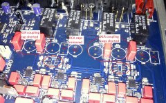
3) had already bypassed the output coupling caps
... I decided to "disconnect" the RCA stage which was implied that increases the Diff filters' output load and subsequently influence THD distortion. Hence I removed U61/U57 and C6/C48. C293 & C299 were already removed.
I played the system with the remaining 49720s on. The sound was felt with increased detail in highs and micro-dynamics, but not a day night/difference.
Then I moved on to replace the 49720 with OPA2211. All well with the SMD job however the sound was coming out distorted on the highs. This revealed that one of the 4 opamps was baking hot. Removed and resoldered and the it was absolute fine. I played some sample tones via USB tones and I did not notice any oscillations on the output, which was quite reassuring. The opamps are running also much cooler. 😉
The sound & stage appears to be on par to 49720 however fatter on base notes... at least it is not worse to my ears, so I'll let it burn for awhile.
A big PLUS of the opamp change is that box temperature has dropped to a point that I can keep my finger on the opamps and regulators' aluminium alloy for more than 15'' without any discomfort... comparing to 5'' before that was already a painfull experience.
1) since I am using XLR->RCA using only (R+,GND) & (L+,GND)
2) all 6 x LME49720 were getting too hot
3) had already bypassed the output coupling caps
... I decided to "disconnect" the RCA stage which was implied that increases the Diff filters' output load and subsequently influence THD distortion. Hence I removed U61/U57 and C6/C48. C293 & C299 were already removed.
I played the system with the remaining 49720s on. The sound was felt with increased detail in highs and micro-dynamics, but not a day night/difference.
Then I moved on to replace the 49720 with OPA2211. All well with the SMD job however the sound was coming out distorted on the highs. This revealed that one of the 4 opamps was baking hot. Removed and resoldered and the it was absolute fine. I played some sample tones via USB tones and I did not notice any oscillations on the output, which was quite reassuring. The opamps are running also much cooler. 😉
The sound & stage appears to be on par to 49720 however fatter on base notes... at least it is not worse to my ears, so I'll let it burn for awhile.
A big PLUS of the opamp change is that box temperature has dropped to a point that I can keep my finger on the opamps and regulators' aluminium alloy for more than 15'' without any discomfort... comparing to 5'' before that was already a painfull experience.
Attachments
Last edited:

- Home
- Source & Line
- Digital Line Level
- Opening the new DacMagic????