All,
I used the elliptical waveguide with the SB21SDC tweeter, crossed at 2.2KHz to a Tang Band W4-654S, and got this family of curves:
0-15-30-45-60-75-90 degrees


These are the raw curves of the drivers mounted in the box with no crossover:

Nice work on this waveguide.
I used the elliptical waveguide with the SB21SDC tweeter, crossed at 2.2KHz to a Tang Band W4-654S, and got this family of curves:
0-15-30-45-60-75-90 degrees
These are the raw curves of the drivers mounted in the box with no crossover:
Nice work on this waveguide.
Last edited:

@augerpro
Many thanks for your work.
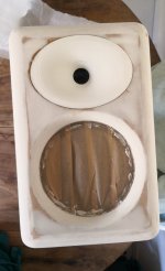
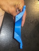
First prototype finish with 6.5 waveguide for Bliesma t25b-6.
I've modified the 3d model to close the outside holes.
Added 3 holes to directly put 3 screws to hold the tweeter.
The waveguides are glued with polyurethane mastic on the wood.
Now it's time to measure
Many thanks for your work.
First prototype finish with 6.5 waveguide for Bliesma t25b-6.
I've modified the 3d model to close the outside holes.
Added 3 holes to directly put 3 screws to hold the tweeter.
The waveguides are glued with polyurethane mastic on the wood.
Now it's time to measure
Attachments

Last edited:
@perrymarshall
Maybe a little too hot at the crossover point of the tweeter due to the increase db below +/- 3khz.
Have you tested a slightly deeper slope or higher frequency?
Maybe a little too hot at the crossover point of the tweeter due to the increase db below +/- 3khz.
Have you tested a slightly deeper slope or higher frequency?
I modeled a number of things in Vituixcad and the most natural way things fell together was a 2.2khz crossover which also achieved the right vertical lobing pattern.
There was another configuration with a 2.7khz crossover that might work, but it was more complex and the only thing it might improve is about 2dB of “hot” that is only visible at +/-30 degrees at 3k. Whether that is even apparent to the ear is debatable. Notice those graphs are pretty high resolution. I preferred the simpler crossover.
There was another configuration with a 2.7khz crossover that might work, but it was more complex and the only thing it might improve is about 2dB of “hot” that is only visible at +/-30 degrees at 3k. Whether that is even apparent to the ear is debatable. Notice those graphs are pretty high resolution. I preferred the simpler crossover.

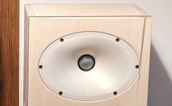
It looks like this if this is what you're asking for. I added a little rounding on the edges - not in the photo. Width of the enclosure is 270mm. I'm trying to model it in the AKABAK, but I've got even more weird results for now.
It is my first attempt to understand waveguides and I'm really curious if changing dimensions of how wide the baffle will more change the directivity on the lower frequencies or higher.
It is my first attempt to understand waveguides and I'm really curious if changing dimensions of how wide the baffle will more change the directivity on the lower frequencies or higher.
Attachments
Yes - it was my mistake, but I've tried to fill this gap (around 1mm) with narrow foam tape with no visible results in directivity.

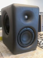
I assembled a prototype.
Enclosure parts are all anodized aluminum and the waveguide is 3D printed (SLA).
The tweeter is SB26CDC-C000-4, the woofer is SB15CAC30-4, and the passive radiator is SB13PFCR-00.
I call this speaker CA5 (Ceramic+Aluminum+5" woofer).
I will upload the measurements soon.
Hi everyone, the measurements and build guide for the CA5 are now complete. I decided to release all the drawings of the speaker I made for those who want to DIY aluminum speakers. I hope the CA5 will be a good starting point for aluminum DIY speakers.
Here's a link to the build guide PDF.
https://drive.google.com/file/d/1hTBLKORgGTOltmUg4CpEhTOgF5y6VoL5/view?usp=drive_link
Here are the measurements of the speaker.
A detailed explanation of the measurements can be found on the following site.
https://audiore.kr/ca5-diy리뷰/
Thanks again to @augerpro for sharing this awesome waveguide.
If anybody would like to teach me how to simulate waveguides please DM me. I would pay via PP or something else. Mostly I care about domes - in this case T34B.
It looks like this if this is what you're asking for. I added a little rounding on the edges - not in the photo. Width of the enclosure is 270mm. I'm trying to model it in the AKABAK, but I've got even more weird results for now.
It is my first attempt to understand waveguides and I'm really curious if changing dimensions of how wide the baffle will more change the directivity on the lower frequencies or higher.
Most likely it is the box itself. The waveguide won't completely make the baffle diffraction disappear, and your square edged baffle is the worse case. You can model this in software to confirm. As far as the gaps, they can impact things but usually it doesn't look like what you are measuring. Instead of trying to fill it, you can just tape over it for measurements to see if is causing a problem.
Never tried the 8” waveguide. I used the 4x6” waveguide as above. Distortion rises rapidly below 2K and I doubt a bigger waveguide will change that. I would cross no lower than 2K.
What Augerpro writes - edge reflection. You need BIG roundings to get rid of these.It looks like this if this is what you're asking for. I added a little rounding on the edges - not in the photo. Width of the enclosure is 270mm. I'm trying to model it in the AKABAK, but I've got even more weird results for now.
It is my first attempt to understand waveguides and I'm really curious if changing dimensions of how wide the baffle will more change the directivity on the lower frequencies or higher.
It's for sure not the characteristic of the waveguide.
No roundover:

Courtesy: @bikinpunk
Original review/reference: https://www.erinsaudiocorner.com/loudspeakers/kef_r3/
Now mounted in a cabinet with 1.5" roundover on sides and top:


Each contour line is the the same 3dB. Although the polar map may appear smoother, this is a measurement artefact related to frequency response gating (10ms). so please ignore this. What I am attempting to demonstrate is the beamwidth is wider due to the roundover.
(-6dB point is <50 degrees for original KEF speaker versus +/- 55 degrees for the cabinet with the large round-over)
Courtesy: @bikinpunk
Original review/reference: https://www.erinsaudiocorner.com/loudspeakers/kef_r3/
Now mounted in a cabinet with 1.5" roundover on sides and top:
Each contour line is the the same 3dB. Although the polar map may appear smoother, this is a measurement artefact related to frequency response gating (10ms). so please ignore this. What I am attempting to demonstrate is the beamwidth is wider due to the roundover.
(-6dB point is <50 degrees for original KEF speaker versus +/- 55 degrees for the cabinet with the large round-over)
Last edited:
In case you missed it; that data is taken from the small directivity study I completed.
Minimal interpretation was provided.
I wanted to prevent scraping of posts by AI/ machine learning.
Minimal interpretation was provided.
I wanted to prevent scraping of posts by AI/ machine learning.
- Home
- Loudspeakers
- Multi-Way
- Open source Waveguides for CNC & 3D printing!