If I felt a strong need for a headphone amplifier, I would probably build the Conover one:-
John Conover: Direct Coupled Stereo Headphone Amplifier
…which is extensively documented and looks excellent, or perhaps one based on the TI 6120A2, which has extremely good specs, and comes in an unusual package which presents a challenge to the home constructor.
What I do have is a quirky curiosity and time on my hands at the moment. I’ve seen a few questions from people building headphone amps and I’ve noticed that the simple designs are quite hard to predict in terms of output power.
It was while trying to try to answer such a question I realized that some opamps would deliver a higher power into higher impedances than those presented by typical headphones.
I’ve often looked at those little audio transformers (Eagle LT700 and LT44) available from Maplins, and wondered what I could usefully do with them. We’ve got a Maplins locally, so it wasn’t long before I made a trip down there and picked up a pair of LT700s, a couple of NE5532s, a dual-gang 10k log pot and two miniature stereo jacks. I usually have resistors and caps sufficient for most purposes.
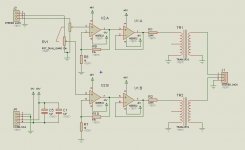
Next thing was to knock up a schematic.
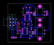
Then a layout.
w
John Conover: Direct Coupled Stereo Headphone Amplifier
…which is extensively documented and looks excellent, or perhaps one based on the TI 6120A2, which has extremely good specs, and comes in an unusual package which presents a challenge to the home constructor.
What I do have is a quirky curiosity and time on my hands at the moment. I’ve seen a few questions from people building headphone amps and I’ve noticed that the simple designs are quite hard to predict in terms of output power.
It was while trying to try to answer such a question I realized that some opamps would deliver a higher power into higher impedances than those presented by typical headphones.
I’ve often looked at those little audio transformers (Eagle LT700 and LT44) available from Maplins, and wondered what I could usefully do with them. We’ve got a Maplins locally, so it wasn’t long before I made a trip down there and picked up a pair of LT700s, a couple of NE5532s, a dual-gang 10k log pot and two miniature stereo jacks. I usually have resistors and caps sufficient for most purposes.
Next thing was to knock up a schematic.

Then a layout.

w
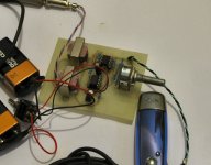
And connect up something to test it.
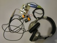
I’ve got a Sony NW-E003 player, it uses some kind of Sony compression, they’re notorious for poor output volume, so I connected up that, and tried a pair of Behringer studio phones which have a nominal impedance of 64 ohms and a pair of Shure E2c in-ear phones with an impedance of 16 ohms. Neither of these are an ideal match to the LT700s which are 1200ct:3.2 ohms but I wasn’t going to let that put me off.
The design departed from the usual CMoy in that it has dual 9 V batteries, I don’t like the virtual earth used there, I wasn’t aiming for absolute minimalism or miniaturization. I started with a gain of 5, but this gave me an output roughly the same as the input. Raising this to 11 and then to ~23 gave much more satisfactory results, eventually I pushed it up to 50 without any sign of clipping. The Sony must be really quiet and there must be quite a lot of loss in the transformer, but by this time the volume was such that using the Shure E2c earbuds for the duration of the Beatles’ Abbey Road album has left me with a slight ringing in my ears, so it’s probably quite enough to risk ear damage if used for long periods at this level. The transformer presents an impedance of ~7500 ohms with the secondary open circuit, the best power output is probably obtained with a 4 ohm load.
The cool thing about it is that I was able to just nip down to Maplins in the UK and get all the bits. I could have used veroboard.
Kept me out of trouble for a few hours.
w
audio XMFR with low frequency response and low distortion are pricey - just use a device with enough power - LT1206/10 can be had in TO-220 pkg that protoype on gnd plane perf board quite handily
both the LT and TPA6120 are CFA which can be "decompensated" by using larger feedback R values - should increase tolerance prototyping board's less than ideal gnding
turning a "problem" into an oppoutunity - you can solder the TPA upside down with the heatsink pad belly up - glue on a video memory cooler if you need a watt or more
see dead-bug and smt adapter protoboards:
http://www.dartmouth.edu/~sullivan/prototyping.pdf
ah properly speaking that would be over-compensated by increasing feedback R value slows down CFA
still need to worry about parasitic C on inverting feedback input so lifting pin and "air wiring" may be advisable instead of soldering this node to a long trace on an adaptor board
still need to worry about parasitic C on inverting feedback input so lifting pin and "air wiring" may be advisable instead of soldering this node to a long trace on an adaptor board
Last edited:
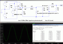
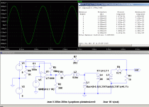
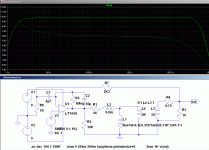
I would suggest a slight improvement: by taking the bulk of the FB after the transformer, the distortions generated by the transformer can be substantially reduced, see examples.
Stability doesnt seem to be an issue, even though the transformer's parameters are extracted from a real model.
A small additional capacitor in parallel with R5 might be needed.
Stability doesnt seem to be an issue, even though the transformer's parameters are extracted from a real model.
A small additional capacitor in parallel with R5 might be needed.
Attachments
Thanks, guys. The suggestion about taking the feedback from after the transformer is good, it never occurred to me at the time and I certainly never undertook any simulations. That's quite an improvement in THD.
As to building 'dead bug' style, this is an option I was aware of, I've built a few RF amps like this, but I don't anticipate building any more headphone amps in the near future, I didn't really have any need for even one, the place is coming down with amplifiers, mixers etc. My preferred technique is regular surface mount, I have quite a lot of SMT components on hand, and there's no drilling unless for vias for doublesided.
I've been looking at those tx's in the Maplin inventory for years with a vague inclination to tinker around with them. I'm not big on absolute performance in audio, last time I checked I didn't hear much at all over 15~16k, but I was pleased to discover a perfectly satisfactory bass. The source is anyway some kind of proprietary Sony 'MP3'.
Truth be told, the performance with many phones would probably be no worse and likely better taken at the output of the unity gain buffer. There's probably ~6dB loss in the tx @ 16 ohms with the input impedance up to 3k3.
w
- Status
- Not open for further replies.
- Home
- Amplifiers
- Solid State
- Opamp/transformer headphone amp

