Different topology - that circuit uses the opamp supply current to drive the output. I use an opamp to drive the output full-swing, by swinging the opamp supply at 2 x input signal.
The opamp's output is thus swinging at 3 x input.
The first opamp provides more initial voltage gain, the second opamp is the floating tripler.
The opamp's output is thus swinging at 3 x input.
The first opamp provides more initial voltage gain, the second opamp is the floating tripler.
I know the idea, i first tried rail bootstrap 5 years ago, i even bootstrapped the power rails of tda1514 which has its own driver bootstrap...i tried all the bootstrapping methods done by Douglas Self with ne5534.I kinda like your circuit though...
Last edited:
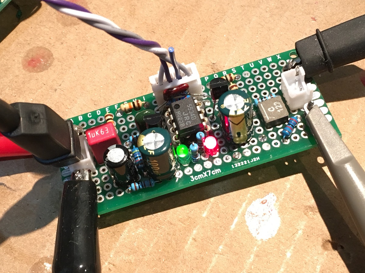
So I've got the opamps (had to make DIP adaptors, only SMT 5534A's in stock ATM, and needed a bit more capacitance to stabilize once the output devices were in the loop(s).

The output devices are the double-die Exicon lateral FETs, ECW20N20/20P20, which I had in stock - thought it would be good to test maximum load for the opamp.
So some testing at moderate power into 8 ohms (I have a current limiting +/-45V supply with max 0.5A output).

Interestingly there is more 2nd harmonic than 3rd, at about -97dB. Without the output devices the 2nd drops below the 3rd, suggesting the output devices aren't well matched(*), or that my biasing arrangement isn't great - its needs a bit of a rethink anyway as an open wiper in the bias pot increases the bias currently.
Happy it basically works.
(*) I don't try to fix the gate capacitance mismatch between p and n devices ATM.
The output devices are the double-die Exicon lateral FETs, ECW20N20/20P20, which I had in stock - thought it would be good to test maximum load for the opamp.
So some testing at moderate power into 8 ohms (I have a current limiting +/-45V supply with max 0.5A output).
Interestingly there is more 2nd harmonic than 3rd, at about -97dB. Without the output devices the 2nd drops below the 3rd, suggesting the output devices aren't well matched(*), or that my biasing arrangement isn't great - its needs a bit of a rethink anyway as an open wiper in the bias pot increases the bias currently.
Happy it basically works.
(*) I don't try to fix the gate capacitance mismatch between p and n devices ATM.
Few people in the high end business would admit today that this is the best you ever need and that you already hit a limit under which no person on Earth can distinguish any harmonic distortion at all. Congratulations! I think i'm gonna make a copy of your circuit one day.It's inspiring!
I still need to work up to higher power testing and checkout the clipping behaviour etc, and figure out if any protection circuit is needed.
I'm also in two minds about whether the tripler opamp should just have local feedback or be part of nested loops - I can see arguments both ways.
Been listening to it through a real speaker today for the first time, monitoring with a 'scope for any RF nasties. Sounds excellent of course, though I run underbiased to keep the small heatsink at a reasonable temp. Thermal camera says about 50C max on the board, and output devices are running about the same.
Well I'm quite happy with +/-9V phono preamp, given that yield about 12V p2p...
I've been simulating multi-stage amps where the opamp sections are chained, the first being gain of 3, the next has gain 5/3, the next 7/5 - result gain of 7 taking +/-15V to +/-105V. The rails of each section cleverly just overlap with the neighbours at full swing.
The basic idea of bootstrapping the opamp from the average of its input and output voltages seems quite flexible, but care is needed to ensure no single stage can ever see the entire signal voltage under fault conditions - in particular the output opamp needs a high value resistor on its output to limit current I think.
Of course having a circuit clip benignly in simulation is a different matter from the real circuit being reliable in the face of repeated power cycles and clipping.
At least the opamps can be socketed for easy replacement 🙂
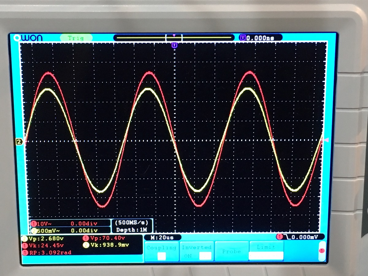
Have you considered bootstrapped opamps? I got 70Vpp with addition of $1 worth of parts to a 5532.
Surjan Dogran's Easy Peasy 70v peak-peak Opamp for $1
Jan Didden suggested that with addition of two zener diodes, the output swing cound be doubled to 140Vpp.
Surjan Dogran's Easy Peasy 70v peak-peak Opamp for $1
70Vpp (red trace):
Surjan Dogran's Easy Peasy 70v peak-peak Opamp for $1
Jan Didden suggested that with addition of two zener diodes, the output swing cound be doubled to 140Vpp.
Surjan Dogran's Easy Peasy 70v peak-peak Opamp for $1
70Vpp (red trace):
Merlin's GlassBlower gets 12Vpp from one 9V battery.
The Valve Wizard
All the parts can be picked for 36V total supply, so about 48V peak to peak.
The Valve Wizard
All the parts can be picked for 36V total supply, so about 48V peak to peak.
Excellent links I don't think i'd seen before, thanks. One of my realizations is that its possible with these techniques to produce amp designs that aren't reliant on the increasingly scarce audio signal transistors, but use stock opamps and as simple output sections as possible (I might try standard n-channel power MOSFETs in quasi-complementary topology for instance).
I still have work to do on biasing schemes, and proving robustness.
It would be nice to have a design using non-obsolescent parts with reasonable performance and a small BOM.
I still have work to do on biasing schemes, and proving robustness.
It would be nice to have a design using non-obsolescent parts with reasonable performance and a small BOM.
- Home
- Amplifiers
- Solid State
- Opamp pyramid stacking for higher voltage operation