I built this gain booster for one of the ways of my active system. It works, but the right and left channels are misteriously mixed: input in either channel finds its way to the other channel as well. The tester beeps when applied to legs 2 (or 1-they are shorted in this circuit) or 7 (output) of each opamp, only when they are powered. No shorted solder on the board. I am using two 8-pin opamps. Happens with different types I have tried it with.
Any ideas?
Thanks in advance
Any ideas?
Thanks in advance
Attachments
Happens with different types I have tried it with.
That's a dead giveaway. You've wired it wrong. Even if there were some weird explanation involving crosstalk in the opamps, the fact that it still happens with different opamps rules that out.
It's on veroboard. Are you sure you've cut all the tracks that need to be cut?
I built a second circuit on another veroboard and it does the same thing. They both work perfectly amplifying the signal as expected without any noise.That's what baffles me the most.
Just for checks I isolated both opamps cutting off the + in to the first stage as well as the output of both stages on the veroboard (on both opamps). It made no difference. Checked many times over. Cannot find anything wrong with the connections.
Just for checks I isolated both opamps cutting off the + in to the first stage as well as the output of both stages on the veroboard (on both opamps). It made no difference. Checked many times over. Cannot find anything wrong with the connections.
If the power supply rails are decoupled, only one power supply should be OK.
Check where the fixing screw shorts pins 3 and 4 together!
Check where the fixing screw shorts pins 3 and 4 together!
Last edited:
What about the possible short circuit caused by the fixing screw on the track with the small ceramic caps?
I will try to post a photo of the underside later.
counter culture: Thanks for helping, indeed. Since I have no electronics training, I needed to be reassured that only a wiring problem can be causing this. I really apreciate your help. The thing is, the circuit is so simple; and by the time I opened this thread I had tested the thing so many times and still could find nothing wrong with it, let alone a crossing of tracks from one channel to the other. I will check again though.
Applying the multimeter from one channel's out to the other, or their negative inputs, or one's out to another's input, while unpowered, yields readings around the 1100 and 1400, but no beeping,tester set for beeping. No reading whatsoever when the tester is set to read ohms in any value range at those points.
Harleyjon: the fixing screw is not shorting anything. I will post a photo later.
Last edited:
When a simple circuit does not work, no matter how many times you check it or rebuild it with new components, this is a fairly clear sign that you have misunderstood something. Your rebuilds include the same mistake. Your checking is simply comparing a mistake on a built circuit with the same mistake in your head, so it always looks fine.
Show us the circuit diagram of what you thought you built - not a vaguely similar diagram using different chips but the actual diagram you used to build from. Then show us what you built.
Show us the circuit diagram of what you thought you built - not a vaguely similar diagram using different chips but the actual diagram you used to build from. Then show us what you built.
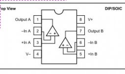
The circuit you gave was for a 14-pin quad amp. You used 8-pin amps (duals or single?). That means 'transposing' pin numbers as you go; very prone to error, and very likely to give the symptoms you have found. That is why I asked for a diagram of what you built, not something slightly different.
When you draw out what you built, or add new pin numbers to your existing diagram, it is quite likely that you will find your mistake.
When you draw out what you built, or add new pin numbers to your existing diagram, it is quite likely that you will find your mistake.
IThe circuit you gave was for a 14-pin quad amp. You used 8-pin amps
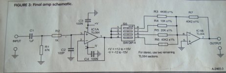
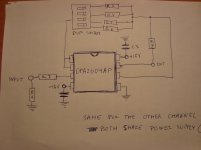
You are right. am using opa2604ap. They are dual. The diagram attached shows the two stages consisting of + and - inputs and the output; plus voltage supply.
Only difference with the quad is -v is on pin 11 in the quad but on pin 8 in the 2604. Also + and - pins are in inverted position in this opamp compared to the quad.
Again, they are functioning correctly (except for the mixed channels, of course), clean sound,very little heat.
Attachments
I have just drawn a diagram. I won't have the camera back until tomorrow so I will post it then.
I just rigged the same circuit on a prototype board and it does the same.
Obviously you guys are right. Something in my adaptation of the original circuit to 8 pin opamps is fishy.
I just rigged the same circuit on a prototype board and it does the same.
Obviously you guys are right. Something in my adaptation of the original circuit to 8 pin opamps is fishy.

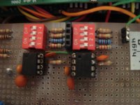
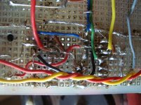
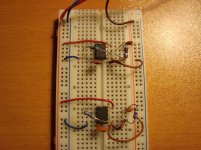
The bottom photo seems to show a black wire from pins 1&2 of one opamp (output and inverting input tied) directly to pin 6 (inverting input) of the other IC, have I got that right? If so, that doesn't look right.
Poldus, you are quite right, the Veroboard you are using is a type of which I have never used. I use the continuous strip type and use a cutter to break the track. See Buy veroboard online from RS Components
You could of course use the TL084. An exceptional op amp and all in one packet.
You could of course use the TL084. An exceptional op amp and all in one packet.
Last edited:
[QUOTEThe bottom photo seems to show a black wire from pins 1&2 of one opamp (output and inverting input tied) directly to pin 6 (inverting input) of the other IC, have I got that right? If so, that doesn't look right. ][/QUOTE]
Although they seem to be the same wire, those are two independent wires going to the black socket on the topside photo (so I can bypass the dip switch and remotely select the resistor value for different gain settings) but the socket is empty now.
Here is the diagram and the prototype board without the input resistors and one single 6k resistor from pins 1/2 to 6. Still shorting 1/2 and 6 BETWEEN OPAMPS. Obviously the only common link between the two devices is the power supply. What do you think?
Certainly,I might have to do just that but still hope that someone will explain what's going on here.You could of course use the TL084. An exceptional op amp and all in one packet.
Attachments
- Status
- Not open for further replies.
- Home
- Source & Line
- Analog Line Level
- opamp channels mysteriously mixing ¿quantum thing or me too dumb?