This thread is about all ways to use OpAmp as input stage in power amplifiers.
Let us see your way to do this.
There are many ways to make an opamp control a power amplifier.
There are good ways, I am sure - and less good ways.
I have one way up my sleeve now, but I also have Choctaw in another thread.
Let us see your way to do this.
There are many ways to make an opamp control a power amplifier.
There are good ways, I am sure - and less good ways.
I have one way up my sleeve now, but I also have Choctaw in another thread.

PLenty of examples of production amplifiers that use an opamp as the front end and control. Have a search on the gargler (google) or other sites.
hello @lineup
have a look at this threads, probably you already know some of them:
https://www.diyaudio.com/community/...-amp-in-the-front-end-overview-wanted.286589/
https://www.diyaudio.com/community/...amplifier-using-opamp-as-input-stages.392412/
https://www.diyaudio.com/community/threads/ez-dump-dump-your-current-without-really-trying.263065/
https://www.diyaudio.com/community/...stacking-for-higher-voltage-operation.344195/

The original KM441. Built in 1985, had two 2-channel units, used them to death and decommissioned in about 2005 with dried out caps. Nothing new under the sun even back then, but they were what I was able to build with what I could get at the time.
Attachments

My go at using opamp as input stage and also as VAS: https://www.diyaudio.com/community/threads/nic-opamp-vas-topology.348646/
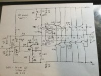
I had known about various designs from supplier datasheets, Elektor and of course some SAC amplifiers, but never in combination with current feedback. Has this particular schematic been discussed here?I like to see a simple but good one with common parts like NE5532 & TIP3055.
View attachment 1376062
First of all, I think it is a smart idea to use the output devices in common emitter configuration with its inherently high output impedance for current drive, as the high output impedance does not have to be generated by feedback alone. Rail voltages can probably be increased by adding cascodes to the op amp supply lines.
What bothers me:
1. The NE5534 is unity gain stable for gain >= 3 without compensation. The output drivers sure add some voltage gain (how much?), and while the closed loop gain is 16 at DC, the 220 nF cap accross the loudspeaker, while surely needed to counteract the inductance of the voice coil, drives this gain to 0 at higher frequency. How is stability maintained?
2. The output stage of the op amp is effectively loaded by < 65 R made up by the two resistors in the supply lines in parallel with the surely lowish and nonlinear input impedances of the power devices. The 5534 will work into 600 R but is happier with 2 K. Running it with this low a load and not providing any buffering or bootstrapping will invite distorition.
Yes, but if the drivers share the same feedback divider, then the drivers clamp each other's EB. SWTPC Tiger amps used two separate dividers which caused the problem and wasted a lot of heat in those resistors. The separate dividers was done for thermal stability but sort of backfired. It can be fixed with diode clamps, but smaller high value resistors and EF's is a better solution.
Better to ask TI engineers...What bothers me:
1. The NE5534 is unity gain stable for gain >= 3 without compensation. The output drivers sure add some voltage gain (how much?), and while the closed loop gain is 16 at DC, the 220 nF cap accross the loudspeaker, while surely needed to counteract the inductance of the voice coil, drives this gain to 0 at higher frequency. How is stability maintained?
2. The output stage of the op amp is effectively loaded by < 65 R made up by the two resistors in the supply lines in parallel with the surely lowish and nonlinear input impedances of the power devices. The 5534 will work into 600 R but is happier with 2 K. Running it with this low a load and not providing any buffering or bootstrapping will invite distorition.

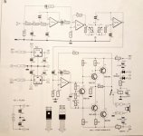
Quad 405 is my favorite.
For Quad 405, the opamp at the front serves two purpose.
1. Provides some of the voltage gain.
2. Serves as DC servo.
For Quad 405, the opamp at the front serves two purpose.
1. Provides some of the voltage gain.
2. Serves as DC servo.

NanoFarad, or anyone else, any links to distortion specs for this beast?
Sorry i don't hve the distortion specs but it works quite reliably. I hve seen it with 5-6 output pairs.
U6 needs a diode from base to emitter to protect against reverse Vbe.
Ed
Ed
- Home
- Amplifiers
- Solid State
- OpAmp as Input in Power Amplifier - exploration