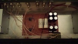
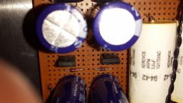
I have a custom preamp with Burr Brown 627 op amps. The unit is great except it seems to have some hi freq. crosstalk. Ill show the layout and perhaps someone would know if they could spot the problem. The soundstage width is very constricted.
Attachments
 Going to relocate this to the appropriate forum; analog line level..
I see no local decoupling on the op-amps.
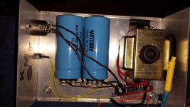
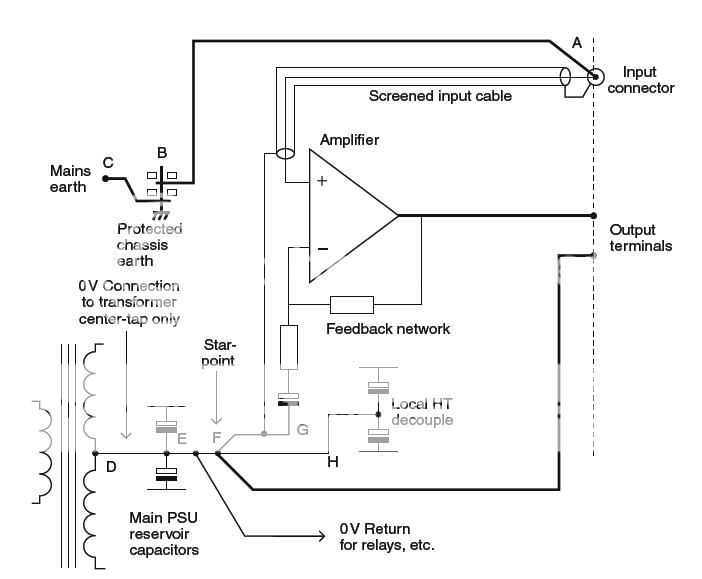
And in the power supply chassis the outputs to the audio chassis should come from the electrolytics, not the rectifier directly - good recipe for additional ripple.
Schematic would be helpful and I wonder about the source selector switch and cross-talk and those other switches, what are they? Grounding configuration may play a role here as well.
The unit is great except it seems to have some hi freq. crosstalk.
To make sure that's the problem, insert a shorting plug into one input,
and see if you get much output while the other channel is playing.
It's oscillating, or on the border of oscillation -- that ratsnest of wiring doesn't help the somewhat finicky, high speed OPA627. There are a couple pages describing proper layout on the datasheet.
I will try the shorting plug test. Also, audio ground is directly on chassis , no 3 pin to earth on unit.
A .01uf quality film cap across the dc terminals of the rectifier, along with another .1uf in series with an 18ohm resistor will help keep hf stuff away from those nice opamps.
Also a .01uf between pins 4 and 7, as close as possible. A film and foil type will be your friend here.
Also a .01uf between pins 4 and 7, as close as possible. A film and foil type will be your friend here.
Has a monoish sound with little separation, restricted soundstage width, although great depth.Sounds like mono in the top octave. Compared with both Mark Levinson No.26s and a passive 10k preamp. Both had great open soundstage width on system.
RMAA plot would be helpful
though even -30-40 dB is actually fine for listening
but poor crosstalk numbers are possibly evidence of electronic problems
though even -30-40 dB is actually fine for listening
but poor crosstalk numbers are possibly evidence of electronic problems
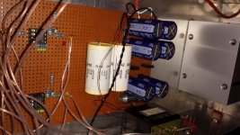
I know the OPA627 has great PSRR but do you have any voltage regulation in your power supply? Any local decoupling? You should have at least 100uF from supply to ground near each power pin on the 627s plus about 0.1uF film or ceramic as close as possible to the power supply pins of the opamps.
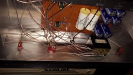
Your signal wiring should either be tightly twisted (signal and return) or, better, shielded.
Your signal wiring should either be tightly twisted (signal and return) or, better, shielded.
With zener diode as reference?
Why not linear regulators 78xx and 79xx, as a minimum level supply for OPA?
BTW working with experimental board is not recomended for precision results.
Ground line around input pins is necessary.
Why not linear regulators 78xx and 79xx, as a minimum level supply for OPA?
BTW working with experimental board is not recomended for precision results.
Ground line around input pins is necessary.
You should just measure the crosstalk to see if that is the real cause... bad sound can be caused by many other things. A computer with a sound card can measure down to -80dB with RMAA software.
There are headphone people that actually force a crosstalk for greater soundstage, just to give an example of how confusing it is to do things by listening and words.
And yea, mentioned already, but that circuit definitely doesn't comply with datasheet requirements.
There are headphone people that actually force a crosstalk for greater soundstage, just to give an example of how confusing it is to do things by listening and words.
And yea, mentioned already, but that circuit definitely doesn't comply with datasheet requirements.
It's oscillating, or on the border of oscillation -- that ratsnest of wiring doesn't help the somewhat finicky, high speed OPA627. There are a couple pages describing proper layout on the datasheet.
When an opamp is on the border of oscillation it's like a regenerative receiver. It picks up any energy, any modulation on the power supply rails (despite the OPA627's excellent PSRR) and pushes it out. The wiring issues which I describe are radiating energy, even just a few microVolts which is cross-fed into the other opamp's circuitry. Address the wiring first.
I am afraid that with perf-board construction the bypass caps act more like radiators or antennas. You could get some 3M copper tape to make a ground plane on which to attach the ground leads of the bypass caps. 3M copper tape is great stuff, can be cut with a Xacto knife or scissors and you can solder to it. Here's a pair of application notes from Analog Devices which may help:
http://www.analog.com/media/en/technical-documentation/application-notes/AN-202.pdf
Analog Devices: Analog Dialogue: Ask The Applications Engineer - 12
I see this unit doesn't have a center tap Transformer. The ground just goes up the XLR cable to the local Reservoir. Not sure if the cable is shielded for the ground or just one of the pins On the input, the ground is just running off of chassis case. The other switches on the front panel are for muting left or right channels. Ill report the result of my crosstalk test later today or tomorrow. Thanks again for everyone's input on this.
The unit only had crosstalk with the input open. Shorting the input, xtalk gone. Close or same L to R and R to L level approx -60db. Starting about 3k with rising response.
BTW Power supply to main unit is unshielded on the cable. Guess i'll go through it per published layout stadards.
BTW Power supply to main unit is unshielded on the cable. Guess i'll go through it per published layout stadards.
- Status
- Not open for further replies.
- Home
- Source & Line
- Analog Line Level
- OPA627 Preamp Dynamic Crosstalk Issue