Fig in post15 is the standard differential input amplifier.
They all have the interference and bandlimiting capacitors in the two signal feeds.
Somewhat surprisingly Whitlock (Jensen) has not shown them in the ESP article.
They all have the interference and bandlimiting capacitors in the two signal feeds.
Somewhat surprisingly Whitlock (Jensen) has not shown them in the ESP article.
Are you referring to the two suggested 100pF caps? If so they are also not included in the ESP design, possibly because when it was designed the bandwidth of the op amps did the job of LP filtering?
Fig in post15 is the standard differential input amplifier.
They all have the interference and bandlimiting capacitors in the two signal feeds.
Somewhat surprisingly Whitlock (Jensen) has not shown them in the ESP article.
Yes, the diagram in post 15 shows the two capacitors.
Both capacitors attenuate interference and C2 also rolls off the HF gain.
I can't see any other capacitors in that diagram.
Both capacitors attenuate interference and C2 also rolls off the HF gain.
I can't see any other capacitors in that diagram.
OK, thanks. While this subject of balanced connections is under discussion, is there a similarly standard circuit for balanced outputs? This crossover has balanced inputs but unbalanced outputs. Since all my equipment and cables are balanced I'd like this crossover to have balanced outputs. I realise that I might not be gaining anything but all the cabling already exists.
Yes, the diagram in post 15 shows the two capacitors.
Both capacitors attenuate interference and C2 also rolls off the HF gain.
I can't see any other capacitors in that diagram.
Jensen's AN-003 gives lots of information.
There are many Jensen papers. W.Jung & D.Self also have quite a bit of info on balanced impedance connections.
There are many Jensen papers. W.Jung & D.Self also have quite a bit of info on balanced impedance connections.
Thanks a lot, I will look it up.
Jensen's AN-003 gives lots of information.
There are many Jensen papers. W.Jung & D.Self also have quite a bit of info on balanced impedance connections.
I already had a 47pF in place so added the second one, it stopped the oscillation completely, total success. I guess I have a higher roll-off point too. Thanks a huge amount to all who helped with this it has made a BIG difference.
While looking around I have noticed that the output buffer opamp is doing the same thing although on a reduced amplitude. I am seeing this as about 5mV p-p noise on the outputs and would love to get rid of it.
This circuit Fig 3 here Linkwitz-Riley Electronic Crossover is a buffer with gain control and unbalanced output, is there a similar simple way to stop this from oscillating?
This will do the trick, I think.
Fig 3 should not oscillate at all if you measure at the output side of the 100 ohm resistor. Sometimes odd measurement artefacts can creep into real world testing. If you short your scope probe tip to the probe ground lead you should of course have a clean trace. Keep the two shorted and now touch them on the audio ground point you are using on the circuit. Is the trace still as clean ?
You are right that there isn't much on the output side of the 100R but the noise that is there is definitely largely the same frequency as the sine being seen on pin 2 of U4A. This sine is the same frequency as was seen on the input buffer (which has now been fixed) so I think it might be doing a similar thing.
I will try what you suggest when I can get the various items back together, thanks a lot for your answer.
I will try what you suggest when I can get the various items back together, thanks a lot for your answer.
Fig 3 should not oscillate at all if you measure at the output side of the 100 ohm resistor. Sometimes odd measurement artefacts can creep into real world testing. If you short your scope probe tip to the probe ground lead you should of course have a clean trace. Keep the two shorted and now touch them on the audio ground point you are using on the circuit. Is the trace still as clean ?
In summary
To sum up the whole thread, the caps on the input buffer killed the 2MHz oscillation and removed a lot of the noise. Adding the same value (47pF) to the feedback resistors of the output buffer removed its oscillation a killed the remaining noise on the outputs.
Thanks to all who sorted this out for me!
The main thing is that you got it sorted 🙂
Yeah, it works a treat now, thanks.
Yes. A COG or NPO dielectric should be used. They tend to be quite linear. You should certainly avoid X7R and Z5U dielectrics.
You may also find silver mica caps, and film caps, and they should be good also.
You may also find silver mica caps, and film caps, and they should be good also.
Yes. A COG or NPO dielectric should be used. They tend to be quite linear. You should certainly avoid X7R and Z5U dielectrics.
You may also find silver mica caps, and film caps, and they should be good also.
Thanks, I'd better try to track some down then, I have no idea which sort I have used. They just say 47 and look like the ones in the attached photo.
Attachments
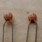
Those are cheapo compressed disc ceramics and if I'm not mistaken, the 'Multicomp' brand. Not an ideal choice it must be said... however can you actually discern an audible difference when substituting something else.
Quite expensive nowadays, these used to be 10 a penny way back yonder,
LCR COMPONENTS - FSC 160V 47PF 2.5% - Film Capacitor, FSC Series, 47 pF, ± 2.5%, PS (Polystyrene), 160 V | CPC UK
The coloured end of caps like these denotes the outer part of the foil, which if you connect to the lower impedance part of the circuit can be used to shield the cap from stray pickup.
The zero tempco ceramic NP0/C0G have a painted black strip across the top of the coating (usually). I have some NP0 with just the number (pF) and not even a voltage code.
Well to be fair to the Multicomp brand ceramics, they are C0G/NP0. I just have lots of practical experience of compressed disc ceramics and how they were a major failure item in generation after generation of equipment going leaky/noisy and so on.
These unmarked one are probably 50 volt DC rated.
http://www.farnell.com/datasheets/1662636.pdf
These unmarked one are probably 50 volt DC rated.
http://www.farnell.com/datasheets/1662636.pdf
I just found out that they came from a Maplin selection box of various value ceramic caps. So probably the cheapest available.
I might well get some of the ones you recommend, a few quid spent to get something quiet and reliable (and hopefully better sounding) is well worth it.
I might well get some of the ones you recommend, a few quid spent to get something quiet and reliable (and hopefully better sounding) is well worth it.
Those are cheapo compressed disc ceramics and if I'm not mistaken, the 'Multicomp' brand. Not an ideal choice it must be said... however can you actually discern an audible difference when substituting something else.
Quite expensive nowadays, these used to be 10 a penny way back yonder,
LCR COMPONENTS - FSC 160V 47PF 2.5% - Film Capacitor, FSC Series, 47 pF, ± 2.5%, PS (Polystyrene), 160 V | CPC UK
The coloured end of caps like these denotes the outer part of the foil, which if you connect to the lower impedance part of the circuit can be used to shield the cap from stray pickup.
These have no other markings than those shown, so I don't know the voltage rating either.
The zero tempco ceramic NP0/C0G have a painted black strip across the top of the coating (usually). I have some NP0 with just the number (pF) and not even a voltage code.
- Status
- Not open for further replies.
- Home
- Source & Line
- Analog Line Level
- OPA2604 - oscillation problem