You are using an out of date browser. It may not display this or other websites correctly.
You should upgrade or use an alternative browser.
You should upgrade or use an alternative browser.
OPA1656 Phono Preamp: Split from OPA1656 thread
- Thread starter JRA
- Start date
I found this bit on breadboarding:
https://forum.digikey.com/t/definitive-guide-to-breadboarding-circuits/36584
Good basic stuff plus links to further tips and techniques. Good God - start with the DIP8 OPA627s you already have and sleep well at night.
https://forum.digikey.com/t/definitive-guide-to-breadboarding-circuits/36584
Good basic stuff plus links to further tips and techniques. Good God - start with the DIP8 OPA627s you already have and sleep well at night.
Not really. Build I built a lot of audio stuff, both for my personal use and for sale.carlmart. Yes. You've be at this for 5-years. Asking for op-amp models, LTspice simulations ad nauseam, searching for and quoting topologies and techniques but you never build anything. Doing a quick search here I see the top three op amps being 1) BB 627; 1a TI 827; and 2) BB 2107 There are your choices. And maybe a BB 1641/42 difet.
Has anyone tried the OPA828 as part of a RIAA preamp?
Having FET input and being reasonably low noise, it looks as a good candidate.
- carlmart
- Replies: 38
- Forum: Analogue Source
Simulations will tell you nothing more. The 627 was introduced by BB in 1989. It was Hi-$$ then as is now. It is still in the general "best of" conversations and forum chatter. (2008+) It is still hi-$$ b/c of curiously continuing demand; TI has to produce it on old fab lines - and they don't like that. Don't quote me.
But you have OPA627s in DIP8! So go for it. But, don't go for an everlasting search for "simulations". Go for the opinions of critical listeners. JMHO.
I have been a professional audio recordist for film & video all my life, so I had a wide experience as a user. Now I'm retired.
In the late '90s I designed and built a portable professional mic preamp for video, using the SSM2017, a short adventure for the US market, and sold them all.
Redesigned a new audio project for video preamp in 2015, using THAT mic balanced chips, and presented it in the Las Vegas annual video show, but it didn't go into production. Just the prototypes.
MM preamps built only discrete ones. Projects by Graham Nalty and Elektor.
Living where I live it became difficult for me to build stuff from the beginning, that is design the pcb and fabricate it all, particularly legit parts. With Brazilian import taxes, importing parts from the USA became very expensive, shipping also did.
So I decided to go a different way. Start from existing Chinese kits and replace the passive parts. That's how I found this thread, and got help from Marcel in modifying the schematic for adding a HP filter.
This week I got the precise Aliexpress pcb that I will use to build the single chip preamp you built.
I will now open a new thread, where I will suggest how to use three different Aliexpress pcbs: a single opamp active preamp, a two opamps with passive filter preamp and a two opamps passive active preamp, as was shown here in this thread.
Gathering all the parts, including regulated supplies choices, has taken a lot of time.
Attachments
Well, I for one was just going on what I saw here - and five years ago, asking the same questions, having things string-out but I am spoiled rotten re my addiction to point-click-and ship, PayPal, 3-day delivery to my door... 0.1% Rs? Sure, how many? That new thread would be interesting.
Comments unasked for re the MOFI approach:
Comments unasked for re the MOFI approach:
Maybe I'll shut up.Do you really think all that front-end RC stuff is necessary?
You probably noticed that the 220uF is out-of place.
I did. My recommendation is - stick with the OPA627.Has someone used the OPA828? Texas claims it to be the successor of the OPA627.
Care to elaborate why? Form factor?I did. My recommendation is - stick with the OPA627.
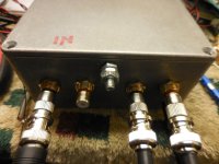
I'm re-doing the RCA in and out jacks on my Marvel preamp metal enclosure. They were too cheap and are very loose-fitting with most or all of the male ICs and adapters I have. I have others now that seem a good bit better. As I've written before what I do is to not use the jack's isolation rings and allow contact between all shields and the metal case. The outboard +/- 15V linear PS is isolated from Earth and its 0V point is bonded to the case and the PCB Gnd, The TT phono leads are isolated as well so the only Earthing is through the IC shields from the 3-prong-grounded main preamp's Line input jacks which are chassis-grounded.
Are there any hard and fast rules on Earthing and/or signal grounding methods in the the case of an external MM phono cart preamp box? I have not ever had audible problems with the above method but was just wondering how the Big Boys do it.
Are there any hard and fast rules on Earthing and/or signal grounding methods in the the case of an external MM phono cart preamp box? I have not ever had audible problems with the above method but was just wondering how the Big Boys do it.
What type of regulation are you presently using with the Marvel preamp?
As I've written before what I do is to not use the jack's isolation rings and allow contact between all shields and the metal case. The outboard +/- 15V linear PS is isolated from Earth and its 0V point is bonded to the case and the PCB Gnd, The TT phono leads are isolated as well so the only Earthing is through the IC shields from the 3-prong-grounded main preamp's Line input jacks which are chassis-grounded.
I usually do the same, and try to keep the area of the loop from the input connector to the amplifier input stage and back via the feedback network small. That is, the loop input connector, C2, op-amp, R12, C8, shield of the input connector.
You can give C8 its own dedicated return wire to the shield of the input cinch connector to ensure that even at low frequencies, the return path is what it should be and not some other ground path. This is useful when there is a relatively strong hum field because the mains transformer has to be in the same case for some practical reason or other. If you are not sure that the connection from the cinch connector shield to the case is always reliable, you can give C8 its own dedicated return wire to the shield of the input cinch connector and connect it to the ordinary circuit ground via a 47 ohm or so resistor as well.
Acopian model DB15-10, +/-15Vdc 100mA
https://www.acopian.com/store/15-(1).aspx
I've bought them used off of eBay if they look good.
https://www.acopian.com/store/15-(1).aspx
I've bought them used off of eBay if they look good.
Can you add to the drawing of your original schematic the different grounding implementations you mention above? Including the enclosure connection and where you connect the original AC transformer input ground.I usually do the same, and try to keep the area of the loop from the input connector to the amplifier input stage and back via the feedback network small. That is, the loop input connector, C2, op-amp, R12, C8, shield of the input connector.
You can give C8 its own dedicated return wire to the shield of the input cinch connector to ensure that even at low frequencies, the return path is what it should be and not some other ground path. This is useful when there is a relatively strong hum field because the mains transformer has to be in the same case for some practical reason or other. If you are not sure that the connection from the cinch connector shield to the case is always reliable, you can give C8 its own dedicated return wire to the shield of the input cinch connector and connect it to the ordinary circuit ground via a 47 ohm or so resistor as well.
Why would you want to put a transformer inside your enclosure or are you asking about an outboard trany with center-tap..?Can you add to the drawing of your original schematic the different grounding implementations you mention above? Including the enclosure connection and where you connect the original AC transformer input ground.
While looking into your suggestions...I usually do the same, and try to keep the area of the loop from the input connector to the amplifier input stage and back via the feedback network small. That is, the loop input connector, C2, op-amp, R12, C8, shield of the input connector.
You can give C8 its own dedicated return wire to the shield of the input cinch connector to ensure that even at low frequencies, the return path is what it should be and not some other ground path. This is useful when there is a relatively strong hum field because the mains transformer has to be in the same case for some practical reason or other. If you are not sure that the connection from the cinch connector shield to the case is always reliable, you can give C8 its own dedicated return wire to the shield of the input cinch connector and connect it to the ordinary circuit ground via a 47 ohm or so resistor as well.
I see a problem in my proto implementation. When driving one channel with my sig-gen with the other channel’s RCA unoccupied while scoping both outputs I see the real output on the driven channel and a much weaker but rather accurate ghost signal being output on the non-driven channel. The separation or aka crosstalk between channels can be as low as 26dB or about normal for a MM cart @1KHz = horrible for a preamp.
The ghost signal is greatest (i.e. least dB separation) when the Left input is driven and both outputs are compared. It is not frequency dependent but the phase relationship does change with frequency.
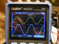
See 1KHz scope shot of 36dB output crosstalk. Yellow = 130mV Right chan ghost. Blue = 8V Left chan driven.
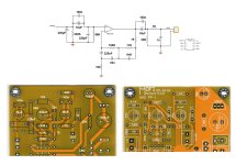
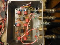
See PC board layout drawing, schematic and pic. The Left driven input goes to the C20/R130 junction, leaves C20 via a short blue wire and terminates at the junction of U2’s + input pin 3 and R60. The Right ghost channel incorporates (as in the schematic) C2/R13, and a long blue wire (orange in pic) from C2 terminates at U1’s input pin 3 and R6.
NOTE: R130 and R13 are 182K input pulldowns and being that R60 and R6 are 63.4K, R130//R60 and R13//R6 = 47K. So leaving the Right input RCA unoccupied is not exactly letting it “float”.
ANOTHER NOTE: I can greatly modify the ghost’s amplitude by orienting the long blue wire (or orange in pic) to the right (increase) or to the left (decrease). Full travel is ~1/2”.
The fear is that my left is bleeding into the right and vice-versa and there’s already plenty of that happening ALL the time inside the cart before the stereo separation even gets to the preamp.
My hope is that somebody can see or suggest just how the Left signal can couple into the Right (despite a 47K Zin pulldown) and vice-versa, to a lesser degree.
Attachments
First off, I don't see how your ground is hooked up, presumably under the circuit board. I'd recommend soldering a hunk of 18 gauge bus wire all along the centre tracks on the PCB since you aren't using them for anything else. At 20 milliohms/metre (6 milliohms/foot in Freedom Units) the end-to-end resistance should be 2 milliohms, low enough for a decent low-Z reference.
What is C2 doing way down there by U2? It should be closer to U1 instead of being by U2 where it could pick up capacitive coupling, hinted by the signal changing in amplitude when you move the wires. I'd recommend moving it beside C80A, which has one end to ground so it shouldn't couple too badly to the input, with the downstream leg where R10 is now, and shifting R10/R11 one hole further down. Then R13 can be hooked up to the beefy central ground rather than being at the end of the side ground, which could be merrily bouncing from currents induced by U2. I'd bet the side grounds are at least 20 milliohms away from true ground, maybe even 0.1 ohm. Run some more bus wire over each of the side grounds to maintain low resistance.
Now your grounding and component placement is more or less sorted then run coax from the input jacks to their respective C2/C20, placing the left input lead outside the lower and left edges of the circuit board. I'm not a huge fan of case-grounded connectors in general and RCAs in particular because they're factories for ground loops when a bit of corrosion intrudes, as it might between the gold plating and the aluminium box. I'd use insulated RCAs for at least the phono inputs and refer the coax shields to the central ground rail, which should be okay since cartridge coils are not hooked up together (apart from parasitic capacitance, of course).
My personal prejudice would be for XLR connectors on inputs & outputs, but it doesn't look like you have too much room in the box for those. Pity. I find XLRs far superior to anything else for signal integrity and a lack of grounding issues when done right, which is why pro audio folks use those almost exclusively.
Good luck!
Can you add to the drawing of your original schematic the different grounding implementations you mention above? Including the enclosure connection and where you connect the original AC transformer input ground.
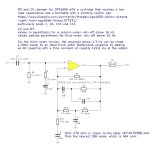
I meant something like this. The shields of all connectors connected straight to the enclosure to hopefully get some RF shielding from it, C8A and C8B getting a dedicated wire to the shield of their input cinch connector (with minimal loop area from the input cinch connector via C2 to the op-amp plus input, to the op-amp minus input, via R12 and C8A & C8B back to the cinch connector), optional resistor Rextra to let everything still work more or less normally if the ground contact from the input cinch connector to the enclosure should be unreliable, other grounds connected somewhere near the output connectors. If you can put the power supply or at least the mains transformer somewhere far outside the enclosure, that helps a lot.
Mind you, I usually need to experiment with it.
Regarding @JRA 's crosstalk: does it get better when you terminate the unused right-channel input with some impedance well below 47 kohm? When you short it, for example?
If so, it might be some capacitive crosstalk from the output of the left channel to the input of the right channel. As the left channel amplifies about 200 times at 1 kHz and the channel separation is roughly at -36 dB, a coupling impedance of about 200 * 47 kohm * 1036/20 ~= 593 Mohm would suffice. That's 0.268 pF at 1 kHz. In this case, I think you have to keep the long orange wire away from the output of the left stage.
If so, it might be some capacitive crosstalk from the output of the left channel to the input of the right channel. As the left channel amplifies about 200 times at 1 kHz and the channel separation is roughly at -36 dB, a coupling impedance of about 200 * 47 kohm * 1036/20 ~= 593 Mohm would suffice. That's 0.268 pF at 1 kHz. In this case, I think you have to keep the long orange wire away from the output of the left stage.
Are you shorting out the 'unoccupied' input or at least using something akin to a cartridge. If the input is open circuit, I'd expect to see 'some' crosstalk.When driving one channel with my sig-gen with the other channel’s RCA unoccupied while scoping both outputs I see the real output on the driven channel and a much weaker but rather accurate ghost signal being output on the non-driven channel. .... The ghost signal is greatest (i.e. least dB separation) when the Left input is driven and both outputs are compared. It is not frequency dependent but the phase relationship does change with frequency.
Only a fully balanced input would show 'low' crosstalk when OC.
First off, thank you DSP_Geek for taking your time to look into this,First off, I don't see how your ground is hooked up, presumably under the circuit board. I'd recommend soldering a hunk of 18 gauge bus wire all along the centre tracks on the PCB since you aren't using them for anything else. At 20 milliohms/metre (6 milliohms/foot in Freedom Units) the end-to-end resistance should be 2 milliohms, low enough for a decent low-Z reference.
For incoming DC look in the upper right-hand corner of the pic and see a black-jacketed cable emerging from a glob of black hot glue. The braided shield (0V mid-point of the +/- linear supply) bonds to a nearby through-wall bolt/nut and lock washer. On the backside please see the table of symbols for things in the drawing. I have 22ga bus wires running down the "spine" of the board which bridge areas of solder flooding, starting at the top JST connector.
C2: Major brain fart, perhaps. I didn't like that either. See attached with your suggestions but with R10/R11 left alone. However I'm still dismayed with the amount of low-freq coupling. I may also slime all the side-tracks with SnCuAg solder.What is C2 doing way down there by U2? It should be closer to U1 instead of being by U2 where it could pick up capacitive coupling, hinted by the signal changing in amplitude when you move the wires. I'd recommend moving it beside C80A, which has one end to ground so it shouldn't couple too badly to the input, with the downstream leg where R10 is now, and shifting R10/R11 one hole further down. Then R13 can be hooked up to the beefy central ground rather than being at the end of the side ground, which could be merrily bouncing from currents induced by U2
Not necessarily inside the box. The box has no relationship with AC Gnd except when connected to the main preamp. The isolated, outboard linear PS, the TT and cart and the phono pre are all tethered to the main system Gnd via the system's IC shield. That's all true in my system but not always.I'm not a huge fan of case-grounded connectors in general and RCAs in particular because they're factories for ground loops when a bit of corrosion intrudes, as it might between the gold plating and the aluminium box. I'd use insulated RCAs for at least the phono inputs and refer the coax shields to the central ground rail, which should be okay since cartridge coils are not hooked up together (apart from parasitic capacitance, of course).
I get that too. And don't like non-noble Al-on-Au connections. However, if made tight at first, AND there is no vibration or disturbance of the the original bright-metal-to-bright-metal contact then that contact can remain air-tight. A lot of connections under the hood of a car are not gold-on-gold b/c they are designed to be so tight that even under thermal cycling and/or extreme vibration, the tin-on-tin contact does not "fret". Example is the tin-plated, 1/4" Fast-on. But. point well taken.a bit of corrosion intrudes, as it might between the gold plating and the aluminium box.
See attached JRA Marvel phono pre, v2.
Attachments
Yes, but only tried a 1K R across an RCA plug. Ghost gone. But, seems to me at least that capacitance in the realm of 10ths of pF would be abundant. Crosstalk would be rampant.Regarding @JRA 's crosstalk: does it get better when you terminate the unused right-channel input with some impedance well below 47 kohm? When you short it, for example?
If so, it might be some capacitive crosstalk from the output of the left channel to the input of the right channel. As the left channel amplifies about 200 times at 1 kHz and the channel separation is roughly at -36 dB, a coupling impedance of about 200 * 47 kohm * 1036/20 ~= 593 Mohm would suffice. That's 0.268 pF at 1 kHz. In this case, I think you have to keep the long orange wire away from the output of the left stage.