Personally I love externally compensated amplifiers.
Agreed! I was thinking about that recently as well.
The OPA1641 would be slightly better. It has the most stable input capacitance vs. common mode voltage that I've measured on any op amp. When we developed the OPA1656, this was also a major design target for us, and the designer and myself spent quite awhile in the lab with previous CMOS audio op amps (specifically OPA1652 and OPA1688) hunting for sources of input capacitance variation. The end result was slightly better than the previous parts, but we still met some limitations from the CMOS process itself. The dielectrically isolated JFETs on the input of the OPA1641 are superior in this regard.
This article shows the measurements I took on the OPA164x family. The OPA827 measured just as good in this same test and has slightly better AC performance specs.
The performance of the CMOS audio op amps is actually fairly close and maybe slightly better than the OPA627, which was somewhat famous for its performance in this use case.
Do you know if the OPA828 performs like the OPA827 in this aspect?
I must say I still kind of regret the disappearance of the lme49713 for composite amps but all those great opamps you've unleashed in the last years more than make up for it. 😉
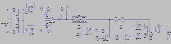
I'm currently busy throwing as many lm4562, opa1642 and opa1656 as I can in a small headphones amp design. 😀
I'm currently busy throwing as many lm4562, opa1642 and opa1656 as I can in a small headphones amp design. 😀
Attachments
Yes, OPA1656 is unity gain stable. Usually (in the last 8-10 years) we only say when an amplifier is NOT unity gain stable (decompensated). The majority of op amps TI is releasing are unity gain stable, although my team did put out the OPA607 recently, which is decompensated.
Unfortunately, we've found decompensated amplifiers scare some customers, and so now I feel like we sell them like the amplifier equivalents of cigarettes (Warning! Only stable in gains greater than 5!). Personally, I love decompensated amplifiers.
I’ve already noticed several references with both versions (G=1 stable or decompensated) like the OPA627/637. I plan to compare their respective sound but, the higher bandwidth of the decompensated version excepted, why do you prefer decompensated Op-Amps ?
Do you know if the OPA828 performs like the OPA827 in this aspect?
Oh man, I'm going to get in trouble for this. I should first mention that I measured a prototype of the OPA828, not the final silicon. I had moved groups before I got a chance to take a look at the final device. But in this ONE regard, I measured the OPA828 performance to be slightly worse than OPA827.
However! In almost every other aspect the OPA828 is likely superior. It's a great part and I know the designer very well and respect him immensely. There was a slight rivalry between that team and those of us working on the OPA1656 at the time, but they really did make a good amplifier.
I should also give the caveat that "slightly worse" still puts it in the top 3 devices I ever measured in this test. Just OPA164x and OPA827 had a slight edge over it. My test was very simple, amplifier in a gain of 1, 10kOhms in series with the input, and a 5Vrms input signal.
I’ve already noticed several references with both versions (G=1 stable or decompensated) like the OPA627/637. I plan to compare their respective sound but, the higher bandwidth of the decompensated version excepted, why do you prefer decompensated Op-Amps ?
OPA627/637 was released in the '90s, my comment was really in regards to more recent releases.
I like decomps because that extra loop gain means lower distortion and better PSRR. Furthermore, the smaller compensation capacitor usually means better slew rate for a given power level. Also, if the unity gain stable version used degen on the input pair to get by with a smaller comp cap, then the decomp version usually does away with that and gets lower noise. For example compare the OPA836 and OPA838.
OPA627 = $28.69; OPA827 = $10.80; OPA1656 = $2.72; OPA1642 = $2.08
I guess if you're in the "I-have-so-much-money-that-it-don't-matter gang", the 627 and 827 are viable options. BUT, for the rest of us, they're not even on the table for discussion!
I guess if you're in the "I-have-so-much-money-that-it-don't-matter gang", the 627 and 827 are viable options. BUT, for the rest of us, they're not even on the table for discussion!
Oh man, I'm going to get in trouble for this. I should first mention that I measured a prototype of the OPA828, not the final silicon. I had moved groups before I got a chance to take a look at the final device. But in this ONE regard, I measured the OPA828 performance to be slightly worse than OPA827.
However! In almost every other aspect the OPA828 is likely superior. It's a great part and I know the designer very well and respect him immensely. There was a slight rivalry between that team and those of us working on the OPA1656 at the time, but they really did make a good amplifier.
I should also give the caveat that "slightly worse" still puts it in the top 3 devices I ever measured in this test. Just OPA164x and OPA827 had a slight edge over it. My test was very simple, amplifier in a gain of 1, 10kOhms in series with the input, and a 5Vrms input signal.
Thanks for the info, interesting to note. Hope you don't get in too much trouble 🙂.
@Johnc124: I looked at that OPA1641, specifically the very constant input capacitance, which is of importance for the CM distortion of a non-inverting configuration.
I was wondering, is the issue the variation of the capacitance with level that causes the CM distortion, or is there another factor related to the linearity of that capacitance? In other words, if the capacitance was absolutely constant, would that be enough to make the CM distortion zero?
Jan
I was wondering, is the issue the variation of the capacitance with level that causes the CM distortion, or is there another factor related to the linearity of that capacitance? In other words, if the capacitance was absolutely constant, would that be enough to make the CM distortion zero?
Jan
As the common mode input voltage swings up and down, the VCE (VDS) of the input long tailed pair devices swings up and down too. This changes their output conductance, and their collector-base (drain-gate) capacitance, and their power dissipation. Unless the LTP are bootstrapped cascodes a la OP-07.
If the current source in the tail of the LTP is imperfect (has noninfinite output resistance), changes in the common mode input signal create changes in the tail current, which creates changes in the output current of the LTP.
If the current source in the tail of the LTP is imperfect (has noninfinite output resistance), changes in the common mode input signal create changes in the tail current, which creates changes in the output current of the LTP.
Anybody has any info on the OPA1611 distortion vs. load resistance?
I guess current-wise it can easily drive 600 ohms, but I would expect the distortion to be a bit higher than when it drives, say, 2k.
There is a graph in the data sheet but that's hard to read. Maybe someone has actual measurements?
Jan
I guess current-wise it can easily drive 600 ohms, but I would expect the distortion to be a bit higher than when it drives, say, 2k.
There is a graph in the data sheet but that's hard to read. Maybe someone has actual measurements?
Jan
Last edited:
Is there a single-channel version of the OPA1656?
They're working on it! Stay tuned.
@Johnc124: I looked at that OPA1641, specifically the very constant input capacitance, which is of importance for the CM distortion of a non-inverting configuration.
I was wondering, is the issue the variation of the capacitance with level that causes the CM distortion, or is there another factor related to the linearity of that capacitance? In other words, if the capacitance was absolutely constant, would that be enough to make the CM distortion zero?
Jan
As Mark mentioned, we do usually bootstrap the LTP cascodes which helps a lot. Of course you also have to look for other sources of non-linear junctions on the input, like ESD protection. And on JFETs, if you're on a JI process you're going to have the back gate to substrate capacitance.
The tail current source is really an area of focus as well, of course you can cascode that if the input voltage range requirements allow for it. You can put a feedback loop around it too. And there are other tricks as well that are a bit more proprietary, one of which on the OPA1656 I believe is still patent pending. I'll post the patent number here if I can find it.
Of course, in rail-to-rail input op amps you have input crossover distortion that occurs when the input signal transitions from one input stage to the other. But this usually doesn't show up in audio op amp circuits running off of +/-15V supplies.
To me, the bigger question is are these source of distortion significant compared to the additional distortion created when the amplifier is used in an inverting configuration. Comparing signal gains of magnitude 1 and low source impedance, the inverting amp will have 6 dB less loop gain, and the output stage will see the load of the feedback resistors. In most of my testing of modern op amps those source of distortion were generally worse than any sort of common mode distortion (with low source impedance).
You definitely could, reduce R4 by a factor of 10 and increase C4 by a factor of 10 to try to maintain low frequency performance. But for MC phono pre-amps a low noise bipolar input op amp like the OPA1612 would give the best noise performance.
Although, I have to think that all of our hard work achieving ultra low noise in phono preamps goes out the window as soon as the needle touches the vinyl, and circuit noise is swamped by mechanical noise in the system. Give it a try!
Thank you for your precious replies!
I'll indeed test this OPA1656 in a MC phono stage and compare it with the INA217 which I'll have to buffer as I need to drive a 600 Ohm load up to its output voltage swing limit : as the INA217 is a close-loop design, can I simply add the open-loop BUF634 unity-gain buffer to its output to boost the limited output current ?
By the way, is the OPA1656 able to drive 600 Ohm loads alone up to its full output voltage swing capacity ? I'd guess that it could but not in Class-A...😕
If you want to add a BUF634 (really I would suggest the BUF634A, cheaper and better) to the output I would suggest switching to the INA163 since it has the sense pin which allows you to close the feedback loop around the BUF634A. If there is no feedback around the BUF, distortion will be somewhat high.
OPA1656 should be able to do about 12Vrms / 17 Vp into a 600 ohm load, but distortion will definitely be rising at that point, as shown by Figure 8 in the datasheet.
How is the BUF634A compared to the LME49600 in terms of distortion, when used in combination with an op-amp?
I used the LME49600 in combination with LME49990 in the Audio Analyzer that I developed a few years ago (RTX6001). The performance I got was rather good.
The distortion numbers shown in the BUF634A are not at the same level, but is that due to the op-amp used or is it caused by the BUF634A?
Would a combination of OPA1656 and BUF634A be able to compete with the LME49990/LME49600 combination in terms of performance (mainly distortion)?
I can see that the BUF634A is now coming in thermally improved packages, which certainly expands the use cases.
- Home
- Vendor's Bazaar
- OPA1656: High-Performance CMOS Audio Op Amp