Maybe you should study the datasheet. It states that 10uF ceramic is the minimum output capacitance for stability.I wonder why my LT3045 regs do not like higher capacitance. It is much better with values below 10uF.
Also this should explain why larger capacitors (e.g. elkos) do not work:
The last sentence is actually why I was surprised that lower values got me better sonic results. With the LT3045 on the AK4493 it has been confirmed that taking out the 100nF close to the supply pins measures better. So much for Data Sheet recommendations.
Actually I am taking about local capacitance right at the to be supplied device. My regulators from LDOVR got the caps you are talking about already on the board.
Local capacitance adds to the output capacitor. LT3045 does not benefit from large output capacitors and no need for larger than 100nF bypass capacitors at VRef of AK4493. So nothing special in your setup.
There are a couple of DIY projects here on the Forums, which implement the Rhom appnote's approach. Search for "Chop Chop Box".
If I needed 1 clean Watt for my 107db w/m mid/high horn how many of the OPA1656 would I have to run in parallel?
You'll need 25 packages to stay within the die temperature guidelines. Whether you use those packages as 50 opamps or 25 opamps (since OPA1656 is a dual), is your choice. The limitation is thermal not electrical.
That minimum capacitance is not a recommendation but a requirement for stability.
As a developer working on LDOVR boards, I can confirm the necessity of the output capacitor to ensure stability. Insufficient capacitance can lead to ringing and introduce output noise (although the correct output voltage may still be maintained). However, the required capacitance is also contingent on the output voltage. Lower output voltages can function with reduced output capacitance. Based on our experiences, LT3045-based boards with 10uF XR7 output caps (Murata GRM series) haven't encountered issues. Nevertheless, if the output voltage is below 5V, a lower output capacitance may suffice. Additionally, it's worth noting that larger output capacitors do not pose any adverse effects.
And that might be the root cause... never parallel differently sized low ESR ceramics when there is any trace inductance. The local 100nF will form a tank circuit with the inductance to the main cap, with the peak often located in the 10Mhz region and the impedance rising to several ohms. Pulse current on the 100nF -- like from Vref of an AK4493 -- will excite the tank circuit exactly at those frequencies.Actually I am taking about local capacitance right at the to be supplied device. My regulators from LDOVR got the caps you are talking about already on the board.
For LT3045 series, I tend to use one single distributed and augmented plane capacitance. That is, a good dozen of 1uF 0603's caps stitching together the continuous 35µm GND and POWER planes evenly over the whole area and of course always directly at the consumer devices and the regulator. Both the regulator and all the consumer devices will see a very low inductance and low-ESR capacitance with zero ringing. Preferable the regulator is located near the center of the plane and near the most sensitive consumer(s).

You lost me on that one. What does "distributed and augmented plane capacitance" mean?
Where do you find space to parallel 12 ceramic caps? Or do you mean stacking?
I usually put the regulator on little feet next to the to be supplied chip. The LT3045 boards are just 25mm X 50mm.
Maybe I should take off the output cap on the boards and just use the Silmic II on the dac board and do likewise with the OPA1656.
Greets Klaus
Say you have two DAC chips and one ADC on a PCB. For economic reason you might want to use one single 3.3V regulator to provide power to all the Vref's, the oscillators etc. Then a good power + GND plane design is the natural choice to distribute the supply voltage as it already forms a high speed capacitor notably when there is only a thin pre-preg between the copper layers for the planes.You lost me on that one. What does "distributed and augmented plane capacitance" mean?
Where do you find space to parallel 12 ceramic caps? Or do you mean stacking?
And this basic plane capacitor can be made much larger and more effective by adding lots of stitching capacitors evenly distributed and at the hot spots, all equal size and type. A dozen or so of 1uF/25V 0603-sized caps don't take up too much board space, IMHO.
When you measure the supply impedances right at regulator, the DAC (or whatever) chips etc you'll find almost textbook-perfect behavior, assuming a decent layout (wrt vias, 35um copper inner layers etc). The nice thing is that the power plane now also is a perfectly valid RF GND plane, albeit with a DC offset. Think of it as a DC level-shifted but otherwise perfect GND plane for RF return currents.
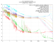
Excessive output capacitors will be punished by an output voltage noise peak.
Output impedance of opamps and regulators looks slightly inductive, a consequence
of their 6 dB/octave gain drop. Still, the LT30xx family is in a class of it's own, but
if you are after minimum noise, you should damp at least the large capacitors.
If all you've got is a hammer, the world looks like a box of nails.
Output impedance of opamps and regulators looks slightly inductive, a consequence
of their 6 dB/octave gain drop. Still, the LT30xx family is in a class of it's own, but
if you are after minimum noise, you should damp at least the large capacitors.
I will use my ears as usual.
If all you've got is a hammer, the world looks like a box of nails.
Attachments
No it doesn't.Does opa1656 draw 100ma?
But as @jean-paul mentioned, it can source 100mA (pos or neg) to a load if necessary.
Jan
Jan didden
Hello, I will install 11 opa1656 in deq2496. Is 2x15 10va transformer enough?
Hello, I will install 11 opa1656 in deq2496. Is 2x15 10va transformer enough?
Attachments
10maDatasheet says 3.9 mA idle current per channel, 100 mA maximum output current.
Attachments
- Home
- Vendor's Bazaar
- OPA1656: High-Performance CMOS Audio Op Amp