Guys, this may have been addressed before, but do the OPA1656 and OPA1655 allow differential input voltages up to the supplies?
The data sheet is ambiguous on it.
Jan
The data sheet is ambiguous on it.
Jan
Wasn't that answered here: https://www.diyaudio.com/community/...ormance-cmos-audio-op-amp.335416/post-7080986
Marcel, not as far as I can see.
In general, FET input opamps can have a differential input voltage that includes the rails.
In some data sheets, that is explicitly mentioned as max DM input level.
In other data sheets it is stated something like 'max input voltage: +/-Vsupply'.
But it is not mentioned whether this is CM only or also DM.
So its ambiguous. I'm about to pull the trigger on purchasing OPA1655's but I don't want to end up with a stash I can't use.
Jan
It says Vcm (V-) to (V+) -2.25V. Next line is CMRR minimum 106dB, typical 120dB WITHIN the aforementioned range. What am I missing?Marcel, not as far as I can see.
In general, FET input opamps can have a differential input voltage that includes the rails.
In some data sheets, that is explicitly mentioned as max DM input level.
In other data sheets it is stated something like 'max input voltage: +/-Vsupply'.
But it is not mentioned whether this is CM only or also DM.
So its ambiguous. I'm about to pull the trigger on purchasing OPA1655's but I don't want to end up with a stash I can't use.
Jan
G²
Vcm means that the inputs, which normally at almost the same voltage in operation, can move up and down to within the supply voltages, as a pair.
If the DM includes the rails, that means that one input can be at one rail and the other input at the other rail without breaking anything.
Jan
If the DM includes the rails, that means that one input can be at one rail and the other input at the other rail without breaking anything.
Jan
According to post #710 that I linked to, there are antiparallel diodes between the inputs, so you can't go further than 400 mV...500 mV without the diodes turning on.
Ahh yes, thanks for jogging my memory Marcel.
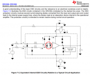
The OPA1642 has protection diodes from inputs to the supplies, so probably can accomodate supply voltage DM inputs, although not specified.
Jan
The OPA1642 has protection diodes from inputs to the supplies, so probably can accomodate supply voltage DM inputs, although not specified.
Jan
Jan,Ahh yes, thanks for jogging my memory Marcel.
The OPA1642 has protection diodes from inputs to the supplies, so probably can accomodate supply voltage DM inputs, although not specified.
Jan
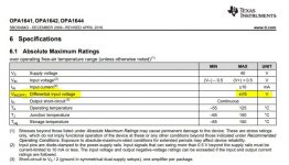
If you take a look at the Absolute Maximum Ratings table in the OPA1642 datasheet it specifies the input differential voltage can reach the supply voltage. As you point out, this is pretty common for JFET-input op amps. The gate oxide of the input MOSFETs on most CMOS op amps can not handle differential voltages up to the supplies. Some CMOS op amps have special protection circuitry which does allow for it though, some examples are OPA192 and OPA189.
Attachments
Yes indeed, thanks John.
As Marcel pointed out, the '16561655 has input protection between the inputs so the DM input is limited to the diode tresholds.
This makes sense for audio applications of course and in no way detracts from the stellar performance.
In my case, there can be a large DM input signal at startup. I blew a couple of OPA172's before realising it ...
Jan
We (the OPA1655/6 designer and myself) experimented with a number of different input architectures, and decided to just keep it simple and stick with the input antiparallel diodes. I'm surprised your signal at startup is able to destroy the OPA172. I had previously found that the CDM ESD resistors (in series with the inputs) on that device made it fairly robust against input differential voltages.
Initially I had 10V zeners in series (opposite polarity) across the inputs, and lost a few OPA172's.
I then replaced the zeners with two antiparallel 1N4148 diodes and had no more issues.
The diodes did impact the distortion of the circuit though so I deleted them again and went with the OPA1642 with no more losses.
I didn't prove that DM input signal at switch-on did destroy them, but the evidence points to it.
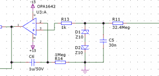
It is a non-inverting servo circuit fed through 32.4Megohm from a circuit running at several kV supply ...
(Zeners are no longer there).
Jan
I then replaced the zeners with two antiparallel 1N4148 diodes and had no more issues.
The diodes did impact the distortion of the circuit though so I deleted them again and went with the OPA1642 with no more losses.
I didn't prove that DM input signal at switch-on did destroy them, but the evidence points to it.
It is a non-inverting servo circuit fed through 32.4Megohm from a circuit running at several kV supply ...
(Zeners are no longer there).
Jan
Attachments
Last edited:
Maybe it is a good idea to divide that 32.4 MOhm resistor in a few resistors and also 1 resistor parallel over C5.
I don't see how this circuit can push more than the rated 10 mA through antiparallel protection diodes between the op-amp inputs, unless several kV means > 324 kV.
Depending on your requirement, maybe apply a resistor between +- opamp inputs in the same way as noise gain is increased for measurements? It shouldn't take much to swamp likely capacitive leakage paths.@marcel: I know. I was looking for some capacitive paths for transients.
For transients, the output connects directly to the inverting input.
That could make the diff input voltage high. I think.
Maybe put a resistor directly in series with the inv input?
Jan
My thought as well. I would actually be more curious what the power supplies of the op amp are doing during power-up.I don't see how this circuit can push more than the rated 10 mA through antiparallel protection diodes between the op-amp inputs, unless several kV means > 324 kV.
- Home
- Vendor's Bazaar
- OPA1656: High-Performance CMOS Audio Op Amp