Just a minute - you have built this, and it works fine. So why are you worried? Just a dose of audio paranoia?
TI's official documents use TINA TI simulation extensively for verification. However, as mentioned earlier, there are problems with TINA TI simulations. Although the actual build works fine, it can be a bit unstable. I found the sound a bit harsh.Just a minute - you have built this, and it works fine. So why are you worried? Just a dose of audio paranoia?
However, there seem to be some problems with the simulation model of TI OPA1622. Since I don't have a company email, I can't give feedback on the TI official forum. I have sent a message to johnc124, but he has not responded yet.
H
HAYK
Use square wave input to see the phase margin of your circuit from the spike hight of the output. If you think the harshness is a matter of stability, apply 20khz input filter and listen, if still harsh, stability is innocent.
1 inch trace is 7.5nH if single trace. If ground traces in parallel, it gets halved.
The positive input must have a grounding capacitor of >100pF.
1 inch trace is 7.5nH if single trace. If ground traces in parallel, it gets halved.
The positive input must have a grounding capacitor of >100pF.
Attachments


Last edited by a moderator:
I checked some information and it is correct that 1mm wire is about 1nh. If there is a ground layer under the wire, it should indeed be smaller.Use square wave input to see the phase margin of your circuit from the spike hight of the output. If you think the harshness is a matter of stability, apply 20khz input filter and listen, if still harsh, stability is innocent.
1 inch trace is 7.5nH if single trace. If ground traces in parallel, it gets halved.
The positive input must have a grounding capacitor of >100pF.
The input is a multi-order filter with fp=20k~22khz. The stability comes from the OPA1622's own loop and has nothing to do with the input.
The inductance generated by the relay is the largest, the combined length of the two contacts is close to 2cm, and there is no ground around it.Use square wave input to see the phase margin of your circuit from the spike hight of the output. If you think the harshness is a matter of stability, apply 20khz input filter and listen, if still harsh, stability is innocent.
1 inch trace is 7.5nH if single trace. If ground traces in parallel, it gets halved.
The positive input must have a grounding capacitor of >100pF.
H
HAYK
https://resources.system-analysis.c...is-there-a-pcb-trace-inductance-rule-of-thumb
It is important as I show, to ground the input with a capacitor.
If the opamp is not oscillating, the input signal controls the behavior. This opamp has 10Mhz loop frequency, it can never get excited by the 20khz signal.
You can bypass the relay with a RC snubber to shunt the inductance.
You can also add a few ohms resistor just at the opamp output.
Attachments

H
HAYK
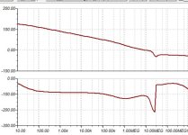
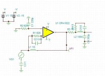
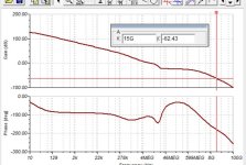
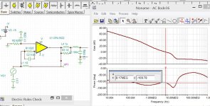
Your test circuit is different from mine, please measure the phase margin the correct way. Nothing can be connected in parallel across the output inductor, as shown in the 1L diagram.You are talking about gain margin, how do you see 7db? I see reaching 180° at 15Ghz with 62db margin.
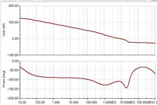
There is another problem. There may be a problem with the OPA1622 simulation model. Under unit gain, the phase margin does not match the datasheet.You are talking about gain margin, how do you see 7db? I see reaching 180° at 15Ghz with 62db margin.
This measurement is not correct. The actual measurement of the headphone cable is 330pf, plus the PCB trace is around 350~360pf, and the inductance is not 0,Please follow the first picture in this post to build itWith 200pF load, the DS says 70° margin, the spice model measures 76°.
H
HAYK
H
HAYK
I think this method is inferior to adding RC absorption, but I'm not sure it will affect the distortion.If 10 ohms is too high apply Thiel 1uH//10ohm, the PM is 70°.
If 10 ohms is too high apply Thiel 1uH//10ohm, the PM is 70°.
Ignore the previous circuitIt doesn't sound great, but the TINA TI simulation shows stability
- Home
- Amplifiers
- Chip Amps
- OPA1622 PCB trace inductance causes gain margin issues