OPA1641 lacks the back-to-back diodes at input so the failure modes of OPA1641 and OPA1611 are not necessarily the same.
You mean like in OPA1611 🙂
There is a difference: unlike those in the OPA1611, the diodes of Hans are not in a common substrate with the op-amp, so any current flowing through them cannot trigger latch-up.
Even the most experienced designers have faced unexpected oscillations with op amps so to accuse other members (who are only here to help you) for daring to suggest that oscillations might be the cause is rather silly.So no, this is not isolated problem just on mine design, or my ignorance, as some members wish for .

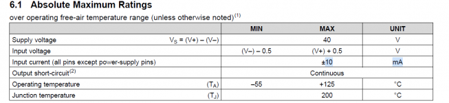
Yes, but OPA161x datasheet also recommends that applications limit the input current to 10mA.There is a difference: unlike those in the OPA1611, the diodes of Hans are not in a common substrate with the op-amp, so any current flowing through them cannot trigger latch-up.
Attachments
The fact that this chip fails on other implementations as well does not prove that your design is flawless. It only shows that the failure mechanism is not understood yet, otherwise there would be some work-around designed in. I got the impression that you are not really interested in a work-around that touches your highly experienced pcb design but better blame TI for the hidden flaws inside this chip.
Last edited:
Yes, but OPA161x datasheet also recommends that applications limit the input current to 10mA.
Assuming the problem is latch-up, and not a random chip failure or some circuit design issue, big external diodes may help to divert the current from the chip and may therefore make triggering more difficult.
By the way, that 10 mA is probably related to electromigration of the wiring of the internal diodes, which is a long term reliability issue. Chances are that much higher currents were used for latch-up testing, 100 mA at the maximum operating temperature is a common target.
Maybe. OPA161x datasheet explains in 2 chapters why input current should be limited to 10mA. I don't like to copy-paste the whole datasheet here so if anybody is keen to know more, please study the datasheet.
So you say that OP amp can oscillate even I tested OP in circuit (and pcb) in various conditions, even extreme ones?Even the most experienced designers have faced unexpected oscillations with op amps so to accuse other members (who are only here to help you) for daring to suggest that oscillations might be the cause is rather silly.
What is than purpose of extended testing of circuit in real life if one can oscillate randomly in avarage conditions?
Some members tend to go out in way that their first assumption is that you don´t know what you are doing, and big companies like Ti and ther products are flawless.
there is also question of implementation of those protecting diodes iniside case of OP, so if they fail, you can throw in the trash whole , maybe vorking OP, current limit of 10mA is funny.
Here is copy paste of answer of other audio equipment manufacturer that I contact with question of OPA failing.
Dear Tomislav,
PH-10 features OPA1611 actually.
I agree with you, unfortunately the latest available products on the market are poor quality we guess because the dramatic shortage of products invited companies and brokers selling even B-stocks or originally rejected parts.
We take care three times more than before using OP amps but n to only because the cases of failures increased significantly.
best regards
Gianni
Sometimes the user of products find issues that haven't shown in testing by manufacturers. Look at newly launched cars and how the customers in the real world very quickly finds a problem that didn't show in millions of miles of testing of prototypes. These things can happen.
The problem you have is that the issue may not be easily reproducible and you also don't want to damage a cartridge in trying to find out. Your options are limited. You could implement a few mitigations in the belief that alone or together they may resolve the issue. Anti parallel diodes on the supply, perhaps some tweak of the input to include a few ohms series resistance, perhaps a few pF added to an input to slow any fast rise time transients. Alternatively consider a different opamp.
Ask yourself what else you can realistically do 🙂
Get real...that's a phono preamp, you're not counting the far infrared photons generated by a star found at 13 billion light years distance...You don´t want to add anything in that place, it is a ultra low level signal input section, you try to avoid every component that can add distortion or noise.
Even parallel load resistors are super low noise type, resistors add current noise, in dynamic signal condition resistor can add another type of of noise as signal changes.
http://pspatialaudio.com/LP_performance.htm
So you say that OP amp can oscillate even I tested OP in circuit (and pcb) in various conditions, even extreme ones?
What is than purpose of extended testing of circuit in real life if one can oscillate randomly in avarage conditions?
I think it was a comment on your attitude rather than on anything technical. There is no need to get upset when someone comes up with a hypothesis that you don't believe to be applicable, just explain why you don't believe it applies instead of continually making remarks like "I'm not a newbie" and
Some members tend to go out in way that their first assumption is that you don´t know what you are doing, and big companies like Ti and ther products are flawless.
I'm not a clairvoyant so I don't know what tests you have performed. I have only seen your layout in post #8 which does not follow the guidelines in the datasheet. If you think your circuit cannot oscillate under any conditions then just say so but without the aggressive tone.So you say that OP amp can oscillate even I tested OP in circuit (and pcb) in various conditions, even extreme ones?
Regarding the quality of parts I have had issues with parts from non-authorised distributors. Never had any issues with parts from authorised suppliers such as Mouser and Digikey (unless the part design was questionable to start with). Never had any issues with OPA161x.
Yes, you are right, what can I do.Sometimes the user of products find issues that haven't shown in testing by manufacturers. Look at newly launched cars and how the customers in the real world very quickly finds a problem that didn't show in millions of miles of testing of prototypes. These things can happen.
The problem you have is that the issue may not be easily reproducible and you also don't want to damage a cartridge in trying to find out. Your options are limited. You could implement a few mitigations in the belief that alone or together they may resolve the issue. Anti parallel diodes on the supply, perhaps some tweak of the input to include a few ohms series resistance, perhaps a few pF added to an input to slow any fast rise time transients. Alternatively consider a different opamp.
Ask yourself what else you can realistically do 🙂
I have already exchanged several emails with Texas instruments people, I will ask if they can check out vendors like Mouser, and if they can send some samples factory direct, so I can test differences in performance. I do have R&S and AP audio analysers and other test equipment.
best regards
You tell us you're not a newbie and can't accept critique, yet you want TI to accept your critique on their design they sell for more than a decade to very big and famous manufacturers that can afford taking TI to court.Now I am in phase of exchanging information with Texas instruments people, I gave them partial schematic of MC section, PCB layout of that section. They didn´t find single error in my design, but refuse to talk about potential problem in OPA16xx design.
First of all you're not able to negociate with TI or Mouser at least to change a batch of faulty components if it is the case.I can understand that , but how are you going to build a long time partnership with TI or Mouser if you get in public with your private messaging ?
From the way you present here I get that you need a reset ...I think you don't have the right skills to talk with TI so you should have looked for a different approach to get at least a different batch of components and make further testing.
When working for a commercial product you need to get out of your "diy skin" and put some bussiness suit on you or you'll face disaster...
@bohrok2610, I didn´t want to sound aggressive, there is always someone who think that knows better and talk with attitude "from above", with no reason.
OK, if you claim that my PCB design is bad, or don´t follow guidelines, please support it with some argument.
If you want design something of your own you can´t just blindly follow all the guidlines from datasheet. I wand to use better components which can be bigger or from other material, dielectric and stuff like that.
My pcb design is fine and simple, I added some points so I can use resistors of various dimensions and combinations, some values that circuit needs are totaly non standard,and they need precision.
Best regars
PS, why I can´t quote your posts?
So you don´t like when someone shares potential problem with community?You tell us you're not a newbie and can't accept critique, yet you want TI to accept your critique on their design they sell for more than a decade to very big and famous manufacturers that can afford taking TI to court.
First of all you're not able to negociate with TI or Mouser at least to change a batch of faulty components if it is the case.I can understand that , but how are you going to build a long time partnership with TI or Mouser if you get in public with your private messaging ?
From the way you present here I get that you need a reset ...I think you don't have the right skills to talk with TI so you should have looked for a different approach to get at least a different batch of components and make further testing.
When working for a commercial product you need to get out of your "diy skin" and put some bussiness suit on you or you'll face disaster..
I just asked did someone encountered same problem, than some people start to interrogate me and my skills without any direct answer to my initial question, and without good arguments about my design flaws.
You talk like someone who have bigger ego problems here, who are "US" to you? Do you represent all the members here?
I posted here to help myself and others with similar problem, not to waste time on some fights with members.
If you don´t belive me that design is stable, I can´t help you.
I did send all details of my circuit and pcb design to Texas instruments development department and they didn´t find any issue in my design.
Last edited:
Apparently @Hans Polak has had similar issues, see https://www.diyaudio.com/community/threads/opa1611-opa1641-dangerous-failures.394933/post-7247997 Unfortunately there aren't any details in his post.
that is good approach, thank you for you time.Assuming a electrostatic discharge triggers a catastrophic latchup - you have two options
1) Keep the trigger impuls off your pcb. I have some experience on this topic and can say this may be very difficult due to the nature of such pulses. Typical ESD pulses have amplitudes of several kV at rise times of 1nsec giving current rates in the ballpark of 10amp/ns. These incredible current rates generate a 10V voltage spike along 1nH - something like 1mm of wire. It is evident that there is no practical way to shunt these even with big SMD MLCC cap or with any clamping diode. All you can do is insert some series impedance that reduces current amplitude.
2) The electrostatic impulse has little energy content and is not destructive per se. It becomes destructive with a powered chip when the pulse triggers internal parasisitc thyristors. If you limit the supply current below the latching current, current flow will stop immediately after triggering and nothing is burned. I propose 47Ohm SMD resistor in each supply line of each IC with local blocking caps of 10nF.
Just my 2c
I did not say your PCB design is bad. I said your layout does not follow the layout guidelines from the datasheet. Post #9 (not by me) already contained a list of layout guidelines which your layout does not exactly follow. Assuming 2nd photo in #8 is your layout for OPA1611 I see these guidelines have not been followed:OK, if you claim that my PCB design is bad, or don´t follow guidelines, please support it with some argument.
- connect a low-ESR,0.1-μF ceramic bypass capacitors between each supply pin and ground, placed as close to the device as possible
- Place the external components as close to the device as possible, keeping RF and RG close to the inverting input minimizes parasitic capacitance.
- Home
- Design & Build
- Parts
- OPA1611 & OPA1641 dangerous failures