Despends on the Mosfets and the stability of the power supply. If those
were lateral Mosfets and a regulated supply it would likely work.
were lateral Mosfets and a regulated supply it would likely work.

I have a bunch of IRF630 I was hoping to use, I will need to be educated as to their 'laterality', the datasheet give no clues. This is new territory for me
Lateral mosfets are of different construction than the IRF types. If it doesn’t mention anything about “lateral” on the data sheet, it isn’t.
International Rectifier don't make laterals anyway. Exicon are one of the few manufacturers left for laterals. Thermal runaway is an issue you are going to have to address - maybe just adding enough source resistance will work, that would be the simplest approach.
Yup - nobody’s getting no 2SJ49/K134 no more…. It’s Exicon TO-247s or the highway.
Regular hexfet and equivalent have the transition from negative to positive vgs tempco at way too high a current to be useful for AB bias.
Regular hexfet and equivalent have the transition from negative to positive vgs tempco at way too high a current to be useful for AB bias.
Lateral mosfets are GSD and vertical mosfets are GDS.Lateral mosfets are of different construction than the IRF types. If it doesn’t mention anything about “lateral” on the data sheet, it isn’t.
The Hitachi lateral mosfet datasheet uses a 1K pot to bias the laterals.
For bipolar or vertical mosfets a Vbe multiplier is best.
Temp Co of enhancements aren't that bad actually
less than BJT.
VBE multiplier could work , numerous circuits to help them
not overtrack. Since temp co of BJT is different.
For such a simple circuit actually diodes would work.
People usually freak out over diode thermal tracking.
This case would help not to over track.
Far as the output topology shown doesn't look too impressive.
But to use all N channel devices you need Quasi design.
Maybe find something different if you require more power.
Far as the one and only Nelson Pass.
Should check out his mosfet version
of the Citation 12
This datasheet shows clear signs of Spirito instability in the SOAR plot: https://www.st.com/resource/en/datasheet/irf630.pdf while this one doesn't: https://www.vishay.com/docs/91031/irf630.pdf In both cases, nothing is specified for pulse widths above 10 ms.
H
HAYK
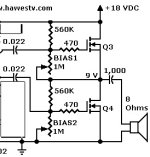
Bias1 adjust the output Vcc/2 it doesn't need thermal compensation.
Bias2 can be done by using a NTC screwed upon the MOSFET, series paralleled resistors adjust the required bias current and drift.
Bias2 can be done by using a NTC screwed upon the MOSFET, series paralleled resistors adjust the required bias current and drift.
H
HAYK
Q3 and Q4 with their DC feedback resistors basically form a kind of voltage divider. I think replacing the 560 kohm resistors with current sources, as was suggested earlier, will only make the DC output voltage less stable.
H
HAYK
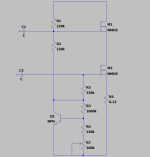
The current source and 39k are related. If you use 10k NTC as this
https://www.aliexpress.com/item/1005003259717722.html
Adjust a series resistor to decrease the drift and adjust the source current.
https://www.aliexpress.com/item/1005003259717722.html
Adjust a series resistor to decrease the drift and adjust the source current.
Attachments

This datasheet shows clear signs of Spirito instability in the SOAR plot: https://www.st.com/resource/en/datasheet/irf630.pdf while this one doesn't: https://www.vishay.com/docs/91031/irf630.pdf In both cases, nothing is specified for pulse widths above 10 ms.
Just for clarification: Spirito instability is a kind of thermal second breakdown that many modern power MOSFETs, especially switching devices with very low on resistance, suffer from. Above a certain drain-source voltage and drain current, a MOSFET with Spirito instability may destruct itself even when it is cooled well, the power dissipation is within the allowable limits, and the external circuit ensures the total current through the device is fixed to some value well below the maximum current rating and that the voltage stays below the voltage rating. If the manufacturer characterized the MOSFET properly, it is shown in SOAR curves as regions where the allowable current decreases faster than inversely proportionally with voltage.
Firstly, thanx for the pointer to the Spirito instability problem! Very interesting. Perhaps DIY audio needs a list of MOSFETs to avoid?
Now about the crude amplifier from http://www.hawestv.com/amp_projects/amp_solid_tube/compl_output1.htm
These amps use RC coupling so the upper FET should be biased with a VCC/2 voltage (+4V vto), ie no pot required. The lower FET should probably have a source resistor. A typical bjt current source might be fine because it has a negative temp co. Or a VBE multiplier with a build out resistor to avoid shorting the gate drive. The amplifier needs a better VAS which would help choose how to drive the lower N channel FET. The typical quasi MOSFET output wastes about 4 Volts for the gate threshold, so this RC circuit is hardly worse. Today, P-channel MOSFETs are not difficult to obtain, so quasi designs are perhaps a waste of time. It is important to bootstrap both sides of the output to avoid wasting output swing on the gate threshold bias. I think Miles has some simple MOSFET amps posted here in DIYA.
Attachments
The amp seems to be very assymmetrical; the upper transistor (Q3) is a follower with no voltage gain, the lower one (Q4), a common source stage with voltage gain. So what if Q4 would be a lateral (lower transconductance than verticals) and Q3 a vertical MOSFET? The lateral MOSFET would also ensure the bias stability via its tempco.Now about the crude amplifier from http://www.hawestv.com/amp_projects/amp_solid_tube/compl_output1.htm
- Home
- Amplifiers
- Solid State
- OP stage biasing