Hello,
Can anyone give me a good op point for the 6au6 to drive a SE 6550 with plate-grid/Schade feedback. I would also like to try the 6gu5 as well, so if there is an op point that will work for both that would be nice. Otherwise, an op point for the 6gu5 would be good. I have looked at the datasheets, and the recommended for the 6gu5 has only 0.4 volts bias.
Thanks a lot,
Chris
Thanks for the link, but I'm not sure of how well it applies to driving a SE 6550. I'm not going to use a diff pair, and I was under the impression that a driver needed more than 3ma of plate current, closer to 7ma when acting as a SE driver with this kind of feedback. Also, while I can see he has about 140v on the screen and 160v on the plate, I can't tell from that how much grid bias there is. And I don't have enough voltage headroom to run DC coupled. Of course, I don't really have a full understanding of this circuit.
So, thanks again, but to clarify, I'm looking for the 6au6/6gu5 as a driver for an AC coupled SE 6550 with plate-grid feedback.
Thanks,
Chris
So, thanks again, but to clarify, I'm looking for the 6au6/6gu5 as a driver for an AC coupled SE 6550 with plate-grid feedback.
Thanks,
Chris
Thanks for the link, but I'm not sure of how well it applies to driving a SE 6550. I'm not going to use a diff pair, and I was under the impression that a driver needed more than 3ma of plate current, closer to 7ma when acting as a SE driver with this kind of feedback. Also, while I can see he has about 140v on the screen and 160v on the plate, I can't tell from that how much grid bias there is. And I don't have enough voltage headroom to run DC coupled. Of course, I don't really have a full understanding of this circuit.
So, thanks again, but to clarify, I'm looking for the 6au6/6gu5 as a driver for an AC coupled SE 6550 with plate-grid feedback.
Thanks,
Chris
I'm building a pair of SE 6550 Schade feedback amps right now. I'm using a MOSFET instead of a 6AU6 but only the voltages are different. It's a version of this circuit built as a complete amp in monoblock chassis to build into my LaScalas...
http://www.diyaudio.com/forums/tube...ar-triode-strapped-pentode-7.html#post2204502
The issue is that the feedback resistor needs to be less than a particular value such that the plate-grid capacitance (internal and external) doesn't cause a HF rolloff. An example with the 6550 is 0.8 pF internal and perhaps 1 or 2 pF external depending on the socket and wiring. I conservatively estimate 5 pF. This is in parallel with the feedback resistor; for a 100KHz Fc you would want less than 318K ohms. In practice I use about 100K. Now you need enough current swing in the driver, if loaded only by the feedback resistor, to allow for the full plate swing.
Assuming 100K and 350V peak swing that's 3.5mA peak current swing needed from the driver. That means the driver needs to idle at something above 3.5mA. In practice using a pentode driver you may want enough idle current to get up into a more linear driver load line. Maybe with a 6AU6 you would want 6-8 mA idle. this can be done with a parallel plate load resistor to B+ without changing the feedback much.
Edit: The driver swing is actually plate swing + grid swing so based on your 6550 load line *** the peak grid swing to the plate swing e.g. 350V plate swing + 20V grid swing is 370V driver swing / 100K ohms = 3.7mA driver current peak swing.
You can plot the approximate driver load line using the idle and peak signal current values vs grid drive voltage on the power tube. I have some examples posted somewhere if you are interested in pursuing this type of circuit. Basically, the driver load line is the key to engineering the current feedback circuit in this topology.
Can you clarify what you mean by AC coupled? can you point to a schematic?
Cheers,
Michael
Last edited:
Can you clarify what you mean by AC coupled? can you point to a schematic?
I think he just means cap coupled... vs... Gary Pimm's direct coupled Tabor design.
Yeah, I was referring to cap coupled. I lashed together a schematic. I know 100k is about normal for the feedback resistor. I guess what I'm looking for is help determining R2, R4 and the driver plate supply and the screen supply. I have looked through the datasheet, and could just used the recommended 250v pk 125v scrn 100 ohm R2, but I don't know what to use for R4.
Thanks
Chris
Thanks
Chris
Attachments
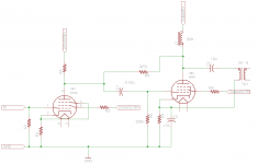
Yeah, I was referring to cap coupled. I lashed together a schematic. I know 100k is about normal for the feedback resistor. I guess what I'm looking for is help determining R2, R4 and the driver plate supply and the screen supply. I have looked through the datasheet, and could just used the recommended 250v pk 125v scrn 100 ohm R2, but I don't know what to use for R4.
Thanks
Chris
Hi Chris,
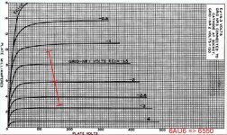
Here's how I go about op point selection for this topology. Starting with the output tube, I look for a B+ and OPT impedance that I like. Knowing it's going to be Schade feedback, I'm expecting a very low effective plate resistance so let's say 3000 ohms Zpri. I like the looks of 340V and 100mA which will give me about 15W Po at the plate for 34W dissipation. It could be run more conservatively of course...
That gives me a plate swing of 300V peak, and grid swing of about 14V positive and 20V negative (Schade feedback will take care of the asymmetric grid swing). That give me approximately 320V peak swing across the Rfb. For a 100K Rfb value, that's about 3.2mA peak current swing at the driver anode.
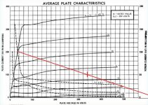
Next I plot the load line of the driver. Looking at the 6AU6 chart I could get a pretty linear current swing around 6-8 mA idle and 150V plate-cathode and 150V g2. Plotting the load line for 6mA idle and 3.2mA peak, with 15-20V peak driver plate swing give an approximate load line shown below. The real load line will curve smoothly over to accomodate increased swing in the negative direction. The driver will also tend to swing more current in the negative direction, which results in a little f2 distortion cancellation or conversion.
Next I look at the input sensitivity and grid bias. If we use self bias the cathode resistor would need to be about 330 ohms. If unbypassed (ideal situation) the input signal peak-peak sensitivity will be about 1.8V of 6AU6 grid swing plus (6.4mA*330R) 2V cathode swing for a total of 3.8V Pk-Pk or about 1.35V RMS input for full output. This is nice, so I would use 330R unbypassed for the R2 in your circuit.
Now I figure the plate resistor or CCS setting. Current through Rfb will be about (340V-152V) /100K or 1.88 mA (neglecting OPT DCR for the minute). We need an additional 4.1mA or so through a CCS or driver plate resistor. I'd use a 47K 2W to B+ for R4 and be done with it. Actually personally I would use a CCS set for about 4 mA but a resistor should be fine. It will steepen the load line of the driver a little bit so at this point I'd go back and re-plot it but that's basically the deal.
Does this work for you?
Cheers,
Michael
Attachments
Last edited:
Does this work for you?
Absolutely, thanks for the awesome explanation. A CCS would be no problem for me, and I have seen the benefits with triodes, but I thought that CCSs and pentodes did not mix. does the Schade feedback change that. I have some boards made for a pimm self bias ccs so I will try one of those set to 4ma.
Absolutely, thanks for the awesome explanation. A CCS would be no problem for me, and I have seen the benefits with triodes, but I thought that CCSs and pentodes did not mix. does the Schade feedback change that. I have some boards made for a pimm self bias ccs so I will try one of those set to 4ma.
The current mode Schade feedback provides an AC load for the pentode, and the feedback resistor provides a DC path to define the idle voltage.
One issue with the CCS may be that the driver plate voltage drifts a little but the DC connected feedback resistor should stabilize it to some extent. I'd set the CCS for 150V on the driver plate and check the voltage periodically to get a feel for the DC stability.
Cheers,
michael
- Status
- Not open for further replies.
- Home
- Amplifiers
- Tubes / Valves
- Op point for 6au6/6gu5 in P-G feedback 6550