I have used " that board with lots of pre drilled holes and square solder for each hole and you just solder them togheter to your circuit " Sorry I dont know the name xD
Also, Im using this op-amp for a small amplifier that I have built ( it has one op amp that drives two small complementary transistors 2sa1015-2sc1815 ( i would like to change them tho, i dont really like them ) and TIP41-42 outputs ) for max 10w-15w per channel
for outdoor use with some nice speakers in my garden .. lol
So one Op amp for buffer , one for the tone control, and another one in the amp ? can I get rid of some ? Wanted to use a " one transistor buffer " with one op amp for the tone control, and one for the amp , I already have some parts avaiable , only two NE5532's tho..and to buy some more I have to pay pretty much for transport, They dont sell in my town. wanted to use what I have, mixing TL072 for buffer and NE5532 wouldnt be great I think ? .
You could try driving the circuit in post 9 direct from your source, volume control after the op amp directly to the power amp. Use a 10k log pot for volume control
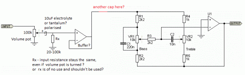
Your circuit in post 21 is OK. The whole idea behind the cap on the wiper is to keep the DC bias current constant. Rx will affect the taper of the volume control and also the input impedance of the circuit will vary with rotation of the control.
Use Rx=100K and your (AC) input impedance will never drop below 50K. And yes you need Rx if you put the cap between the pot wiper and non-inverting input. If the offset voltage is acceptable, then you can skip the coupling capacitor between the buffer and tone control circuit. In fact it's best,because input impedance at low frequencies can dip to 2K2 in the configuration shown. Offset can be improved by inserting a resistor of same value as Rx in the feedback circuit, instead of a direct link between output and inverting input.
I would use 5532 for both op amps. The tone control has very low value resistors (you keep switching that up, it makes a difference) which need some heft to drive.
You can learn to design these circuits yourself. Then you won't have so much grief. I got my chops from Walt Jung's "Audio IC Op-Amp Applications" a long time ago. He breaks it down so you can understand and provides "cookbook" equations and charts. It's an old book and we've come along way since then, but if you mastered it you'd be designing your own circuits instead of using less than ideal circuits on the web.
I actually draw the buffer with Rx and that stuff , wasn't sure if its ok.
"The tone control has very low value resistors" you mean R1-R2-R4-R5 ? changing them will affect frequency " boost/ cut " so I need to change the cap values as well, and he pots?!. What's wrong if they are low value reistors ?. Thanks.
And how can I calculate these resistors and the value of the caps , for different frequencys i want for the bass and treble right ? . Thanks
"The tone control has very low value resistors" you mean R1-R2-R4-R5 ? changing them will affect frequency " boost/ cut " so I need to change the cap values as well, and he pots?!. What's wrong if they are low value reistors ?. Thanks.
The op amp has to drive the resistors. It's part of the load. Plus the input buffer or source has to drive them too. This can affect linearity and also raise the low frequency f3. The one circuit has 1K resistors in the tone control section -a very heavy load for aTL07x chip, don't you think?
Norton and Thevenin equivalent circuits answer all of your questions. That's why I keep emphasizing them. I don't mind helping, but this knowledge will put you in the driver's seat. It's worth learning. Wikipedia even has decent introductory articles about these theorems.
Rod Elliott has an article about this circuit where he describes everything. Have you read it?And how can I calculate these resistors and the value of the caps , for different frequencys i want for the bass and treble right ? . Thanks
This is a super simple, proven circuit. It's been used so much that there should be no mystery. Whatever's wrong with yours must be simple. Again, do you have a 0.1 uF ceramic capacitor soldered directly to the power supply pins of the chip? That's a basic requirement.
- Status
- Not open for further replies.
- Home
- Amplifiers
- Chip Amps
- op-amp tone control help