Hi All,
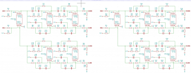
I am trying to power the op-amps in my active crossover (image attached) using the single 24V DC supply for the rest of the board. I initially just had a potential divider but this is insufficient as it can't supply enough current without the virtual ground voltage dropping. Smaller resistance values can be used but this results in large heat dissipation.
I've read that an op-amp can deal with this issue however am unsure how to determine how much current they can supply from the data sheet. I'm also unsure of what value on the datasheet states how much current the op-amps in the active crossover require.
I've also read that if I use a virtual ground it can be an issue that I'm powering other components on the board with the same DC supply but I am unsure of why this is or how to rectify the issue.
Does anyone have a solution to this power supply issue and can direct me on how to understand the current requirements?
Thanks!
Attachments
What values are you using in your voltage divider to create a virtual ground? Is it supported with a capacitor?
If you search for virtual ground circuits you can find better designs. Rod Elliot's site has some from memory.
I also note you've tied your outputs to the -12 rail instead of gnd, not sure if that's an error in the diagram or the way it's designed.
You can sometimes get away from the need for a stiff virtual ground by using a coupling cap at the output. This may not be ideal for a crossover however as it will have an effect on the performance.
Last edited:
All the inputs and outputs must be capacitor coupled in a single supply design, none are shown here.
What crosstalk would you find acceptable between the low- and high-frequency sections and between left and right?
The simplest solution is using AC coupling capacitors on all inputs and outputs and a big decoupling capacitor between the output of your voltage divider and ground. The DC current that the voltage divider has to deliver should be close to zero, but you need a low impedance at audio frequencies to limit crosstalk.
The simplest solution is using AC coupling capacitors on all inputs and outputs and a big decoupling capacitor between the output of your voltage divider and ground. The DC current that the voltage divider has to deliver should be close to zero, but you need a low impedance at audio frequencies to limit crosstalk.
I'm going to take a good stab at this over the weekend.
Looks like the TI document will come in very useful so thanks for that. I have bread boarded this circuit already using the potential divider attached. Whilst the crossover functioned correctly there was an audible chirping due to the virtual ground collapsing as the current draw was too much. Switching the resistors to 100ohm fixed this issue but generated a lot of heat.
I also initially had a 10uF capacitor in parallel with both resistors however the circuit didn't function until I removed the one connected between the virtual ground and the 24V rail. I'm not quite sure why. I'm also not sure what you mean by all inputs and outputs needing to be capacitor coupled.
Attachments
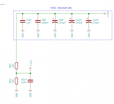
Try 1k resistors, and 100u in parallel with a 100n ceramic in place of the 10u shown. That may be sufficient. If not, use a buffered virtual ground of some kind.
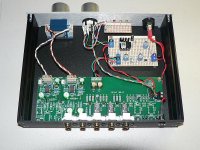
I've used both methods as shown in post #4 but the last one I did used a supply from a Silicon Chip design. Replaced a 317/337 supply that ran from a AC plug pack which resulted in a bit of noise in the pre amp. The pre is now quiet and runs from 12-24VDC plug packs.
The upper section runs the pre amp with 2xLM4562 and the lower section supplies 5V to relays and LEDs. I used 35V caps for the 220uF and 100uF.
It may look odd as it only has a 100uF cap to the -ve rail output and none to the +ve rail output but that's what the SC circuit showed. It's required to keep noise out from the plug pack so it doesn't get into the audio path. One other thing is to never run a device from the rails to the SG 0 virtual ground.... run across the rails such as shown for the 5V supply.
Attachments

Last edited:
Hi All,
I am trying to power the op-amps in my active crossover (image attached) using the single 24V DC supply for the rest of the board. I initially just had a potential divider but this is insufficient as it can't supply enough current without the virtual ground voltage dropping. Smaller resistance values can be used but this results in large heat dissipation.
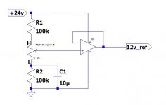
This should be a fairly simple process, a standard LM7812 regulator should do the job nicely. Since the 7812 can deliver up to 1.5 amps it can be used as a device-wide virtual ground and, they're cheap.
A couple of suggestions for your design ...
- Unless all inputs in your system, including the amplifiers are referenced to the virtual ground at +12v you will need to ensure there is a coupling capacitor inbetween each of your outputs and the amplifier inputs
- The resistors from op-amp outputs to ground are not needed and may cause problems with output offsets.
- There are several places where you've used duplicated parts in series. A single 22k will replace the two 11k resistors and work just as well, similarly a single .047uf will usually replace two .1uf parts quite nicely.
Looks like a pretty good project... best of luck with it.
Attachments

Last edited:
You can't use a standard series voltage regulator to establish a virtual ground, regulators cannot sink current.
You need an R/RC divider and opamp buffer (perhaps several buffers). This is totally standard practice and you'll see this everywhere.
However its a bit of a hack, a large piece of equipment like this should have true +/-12V supply rails.
You need an R/RC divider and opamp buffer (perhaps several buffers). This is totally standard practice and you'll see this everywhere.
However its a bit of a hack, a large piece of equipment like this should have true +/-12V supply rails.
Last edited:
You can't use a standard series voltage regulator to establish a virtual ground, regulators cannot sink current.
Good point, thanks for posting it.
Yet, I used to see this in my service work, all over the place. Generally the 7812 would be tied to a relatively large capacitor, or several distributed around the board. It pretty much keeps the caps charged while the caps handle the source/sink duties. The 12 volts then acts as a reference voltage, not a true ground.
You are correct that the only true virtual ground is a voltage divider, not a regulator.
It will work reliably when you just add a resistor from the 7812 output to ground such that it always has to source at least 5 mA. The current sinking is then done by the resistor and the output decoupling capacitors. Mind you, the noise level is probably a lot higher than with a capacitively filtered voltage divider with or without buffer.
I think there are some errors in your circuit. C111 and C113 is connected in series. Similarly R70 and R72. You may need to add a capacitor at the final output unless you are very sure the next stage already has one. Generally it is a good idea to put capacitor before the last 2 resistor as it will load your op amp in DC output. But 100k should be fine .You may not need to add in virtual ground at every stage for low pass filter.Hi All,
I am trying to power the op-amps in my active crossover (image attached) using the single 24V DC supply for the rest of the board. I initially just had a potential divider but this is insufficient as it can't supply enough current without the virtual ground voltage dropping. Smaller resistance values can be used but this results in large heat dissipation.
I've read that an op-amp can deal with this issue however am unsure how to determine how much current they can supply from the data sheet. I'm also unsure of what value on the datasheet states how much current the op-amps in the active crossover require.
I've also read that if I use a virtual ground it can be an issue that I'm powering other components on the board with the same DC supply but I am unsure of why this is or how to rectify the issue.
Does anyone have a solution to this power supply issue and can direct me on how to understand the current requirements?
Thanks!
Careful in your design as a single supply rail circuits can go boop during turn on and can damage speakers as your virtual ground goes from 0 to half Vcc.
Oon
Hi Douglas, thanks for the suggestions.
Would the capacitors in my design such as C115 not act as coupling capacitors? Not entirely sure where I would need to place these caps if there are some missing.
I was looking into regulators but because the power supply to this board may vary (10-24V) I need to guarantee the virtual ground will be half the supply in each instance so fell on the potential divider.
Hi Douglas, thanks for the suggestions.
Would the capacitors in my design such as C115 not act as coupling capacitors? Not entirely sure where I would need to place these caps if there are some missing.
I was looking into regulators but because the power supply to this board may vary (10-24V) I need to guarantee the virtual ground will be half the supply in each instance so fell on the potential divider.
Your life would be SO much easier if you just built a dual (+/-12 Volt) power supply. You have 10
opamps that have a quiescent load of less than 4mA each so a trivial 100 mA supply would deliver
2 times what you need.
The single supply version WILL have a turn on thump as all those caps get charged up so you will
need to add power on mute just to avoid the thump. You REALLY can't have that into the tweeter.
Someone mentioned resistors and caps in series. That is certainly easier than finding exact 2:1
component values to achieve Butterworth response. If you use surface mount it will cost almost
no PC Board space. Just remember caps in series don't add, they divide by 2.
I have done virtual grounds when absolutely necessary (in my car 30 years ago) but under
protest as the added parts are MORE than a dual supply. If I was doing opamps in the
car today I'd add a DC-DC converter to get the negative supply.
That solution could work for you too. If you're worried about switching noise use a +/- 15 volt
supply with linear +/-12 regulators to clean it up. I know with certainty that this approach works
well as I'm using an 8 Volt switcher with a 5 Volt regulator to supply my 5.1 optical DAC on the TV.
The improvement was well over 10dB.
DigiKey has +/- 15 Volt DC-DC converters less than $15.
G²
Last edited:
Hi Douglas, thanks for the suggestions.
Would the capacitors in my design such as C115 not act as coupling capacitors? Not entirely sure where I would need to place these caps if there are some missing.
I was referring to the series chains in each filter with nothing between them... for example: R70 and R72 ... these could be combined into a single 22k resistor. C111 and C113 ... can also be combined into a single .047 uf capacitor. Done across all filters, this would reduce your parts count and thus the risk of interference and failure substantially.
The caps such as C115 and C119 do have a connection between them, so you can't combine them.
I was looking into regulators but because the power supply to this board may vary (10-24V) I need to guarantee the virtual ground will be half the supply in each instance so fell on the potential divider.
If the voltage is variable, yes, you would have to use a voltage divider rather than a regulator. A simple solution for this, as others suggested, is to use an opamp as a low impedance buffer.
Attachments
Hi Douglas, thanks for the suggestions.
I hope you don't mind one more question...
I've been studying your drawing a bit and I'm wondering ... are you trying to implement balanced (xlr) audio?
I was using them in series as it makes matching the resistors/capacitors easier. The crossover is designed for differential audio signals coming from a RN-52 BT audio module. Each of the high/low lines are fed to their own TPA3116D2 Amplifier.
Using a single resistor value makes it easier to get good matching between the R and 2R sections, since you only need one value of precision resistor - reducing the BOM complexity reduces manufacture cost too.
From a tight layout perspective paralleling is more convenient than series strings, ie use 22k and 22k||22k instead of 11k+11k and 11k.
From a tight layout perspective paralleling is more convenient than series strings, ie use 22k and 22k||22k instead of 11k+11k and 11k.
- Home
- Source & Line
- Analog Line Level
- Op-Amp DC power supply