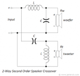
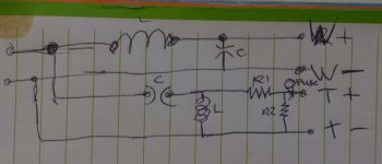
Try squaring the circuit up as in the first attachment and also include the two attenuating resistors in front of the tweeter as in the second attachment.
Let's see how that works out. It can only contribute to the learning process!
P.S. The resistors are 3 ohm and 7 ohm, both rated at 5W power handling.
Let's see how that works out. It can only contribute to the learning process!
P.S. The resistors are 3 ohm and 7 ohm, both rated at 5W power handling.
Attachments
Try squaring the circuit up as in the first attachment and also include the two attenuating resistors in front of the tweeter as in the second attachment.
Let's see how that works out. It can only contribute to the learning process!
P.S. The resistors are 3 ohm and 7 ohm, both rated at 5W power handling.
...Circuit...
Thanks the both of you. So that's how they're supposed to be laid out! I'll have a go for myself now anyways as homework without referring to the second one. Thankfully I don't have a photographic (or thanks to a miss-spent youth, a short term) memory
Once again the internet help a noob and nobody calls him names. Brilliant😀
PS... I have learned enough to through this circuit map and google to know this isn't a first order crossover (lets pretend it wasn't mentioned in the thread already) - The learning process is underway!
Last edited:
Just ignore my attachment showing the resistors. Use my first attachment as a framework and you will eventually arrive at PRR's beautifully interpreted layout.🙂I'll have a go for myself now anyways as homework without referring to the second one.
Just ignore my attachment showing the resistors. Use my first attachment as a framework and you will eventually arrive at PRR's beautifully interpreted layout.🙂
Much thanks dude. Give a man a fish etc...
🙂
+1 for the multimeter that can measure inductance. Or a dedicated LCR meter.
Then draw the circuit in one of the many circuit simulators (TINA-TI, LT Spice, etc.) and simulate its frequency response within the audio band. That should tell you everything you'd want to know.
Tom
Then draw the circuit in one of the many circuit simulators (TINA-TI, LT Spice, etc.) and simulate its frequency response within the audio band. That should tell you everything you'd want to know.
Tom
They would not use costly coils unless it was approximately 2nd-order.
Knowing that, at the center frequency the L, R, and C should all be about the same. L and C to give frequency. R to give Q about unity (0.5-2.0).
The "4 Ohms" may be true or not. In fact it is surely not 4 Ohms over most of its range, but we do what we can.
6.8uFd shunting 4 ohms is a corner near 5.8kHz. We expect the LC to be tuned a little lower. 0.2mH with 6.8uFd is 4.3kHz. That ignores the odd 3r in series with the C which spoils the 12dB/oct high-cut, but why?
The high pass is mysterious from the first. 7 Ohms in front? Whatever else, that makes huge loss into 4 ohm load. Maybe it is a horn tweeter with 10dB higher sensitivity?? So I stuck a coil value on and added gain of 2.5(8dB) to sim horn gain. It is a reasonable curve but it sure is soft about cutting the bass out of the tweeter.
Ah, there are no 4 ohm horns, usually 16, and often higher above 3kHz. I stuck a 20r tweet value and these curves look good for an 8-inch woofer crossing to a small ($20 class) horn tweeter. It has the proper bump-corner and steep slope on the tweet. The woofer top-cut is soft and I don't see why they spent the 50 cents for a resistor.
Attachments
Hope you've room for a school of fish! 🙂Give a man a fish etc...
assuming 4 ohm for both tweeter and woofer, the crossover frequency looks like 4.2 kHz and woofer coil will be 0.15mH, tweeter parallel coil 0.3mH
or else
or else
What impedance do you have to enter in such calculators, the nominal impedance or the average minimum impedance of the driver, please ?
Preferably the impedance of the driver at the frequency of crossover. This may be estimated from manufacturer's impedance versus frequency graph, where available. The experts on this forum do their own measurements. If no other information is available, then enter the nominal impedance. But, I think you may know that.
Thank you Galu, very usefull tip, so ok, at the XO cut off.
One doesn't always want to purchase a driver to measure if not already mase on ZaphAudio or Omnic site... I trust in some companies like Seas, Scan Speak to give the good measurement... Some are difficult to look at dje to the scale or distance measurement as SB Acoustic ...
I see from a Vifa I have at 4 ohms impedance than the xo is in the 3 ohms minimum of the tweeter... Now I will proceed as you said.
Last edited:
Try squaring the circuit up as in the first attachment and also include the two attenuating resistors in front of the tweeter as in the second attachment.
Let's see how that works out. It can only contribute to the learning process!
P.S. The resistors are 3 ohm and 7 ohm, both rated at 5W power handling.
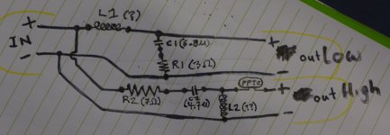
Ok... So life got in the way a bit (maybe a good thing, longer since I saw PPR's layout), but I've finally done my homework. Did I get it right?
In the spirit of show my workings, the first pic is the first attempt, the second one neatened up a little.
Attachments

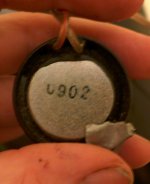
And to the rest of the posters in this thread - thanks muchly. Unfortunately I haven't got the box nor the 6.5" drivers, just the tweeters which say "0902" on the back of each. I suspect it's just a part number. These are nearly 15 years old and the company has moved upscale a bit, leaving out the £140 front door components
A lot of this is above my pay grade, but as I always say - nobody ever got cleverer by hanging around with stupid people. Stuff that goes over my head may one day pop back up when I understand a little more.It' all good stuff.
A lot of this is above my pay grade, but as I always say - nobody ever got cleverer by hanging around with stupid people. Stuff that goes over my head may one day pop back up when I understand a little more.It' all good stuff.
Attachments
Last edited:
Daaaaaaaaam, I wish I still had the 6.5" drivers, those things kicked HARD. Not as refined as the focals in my s2k, but WAY more punch.
Getting there! However, I told you to ignore my attachment showing the resistors, but you haven't and have stuck them where I didn't want you to stick them anymore. 😱Did I get it right?
So, and it's my fault really, you still have the resistors to locate accurately in your otherwise correct schematic!
Getting there! However, I told you to ignore my attachment showing the resistors, but you haven't and have stuck them where I didn't want you to stick them anymore. 😱
So, and it's my fault really, you still have the resistors to locate accurately in your otherwise correct schematic!
Ahhh... I assumed you said leave them out to simplify my homework a little😀
I'll get it figured out, thanks dude.
It could be skating close to the tweeter's own rolloff?but it sure is soft about cutting the bass out of the tweeter.
...Getting there!...
...resistors to locate accurately in your otherwise correct schematic!
Ok, I must admit - without checking PRR's schematic I had a hell of a time working out where the resistors went. I quickly realised I am NOT a natural at this.
So I copied out the schematic posted by PRR (many thanks, would have taken all day otherwise)... Just because education was at least 50% (probably way more), and to learn, some sort of homework learnings were needed, I decided to swap about the HF and LF outputs... All my attempts so far have been LF on the top bunk, HF on the bottom bunk.
And yes, it turns out I'm even more of a total beginner than I thought, first ever attempt at it (excuses excuses) that STILL caused me some trouble. Like I say... I'm really really REALLY not a natural at this stuff! It was quite surprising how hard I found it actually - I'm regularly repairing massive machines in work and their "schematics" (usually hydraulic oil circuits, linkages, parts diagrams etc) rarely cause me any trouble. Just flipping the outputs from the PRR orientation to the jjams orientation design caused all manner of confusion.
Anyways, I submit my homework... Please tell me I didn't fork it up. I beg you...
Attachments
- Home
- Design & Build
- Parts
- Online crossover calculator - in reverse?