I got this one from eBay for 170 Euro incl. post two and a half years ago. I have done some on and off work in it since then. Thought to report here for any cassette decks lover having one and googling.
My findings:
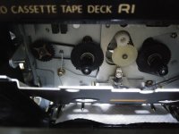
251mm L (9.9") or 80mm Diam. capstan motor belt of 5-6mm width seems right. PRB FRW9.7 246mm worked bit better than FRW9.6 244mm. Back tension belt is 25mm Diam. square section, about 1mm wide. Belt it came with was crap and narrow off-riding the pulley. Back tension belt was missing. Found a melted blob behind a flywheel. Should have been its remains.
After cleaning, lubing, new left pinch roller standard practices, mechanical alignment was done with M300 gauge, Sony Mirror Cassette, TEAC Torque cassette.
Measured bias freq ~110kHz
Source loop THD measurement at +5dB red or 2V RMS with original Q221 2SD655F mute 5V VEBO 0.15%. replaced with 2SD1302S 12V VEBO 0.12%
REC/PB ref match at REC CAL level panel pots +0.6dB for RTM FOX C60 Type1. Chosen because new production with a spec sheet.
REC CAL level panel pots range +5/-3dB
Positive notches +1dB each
Negative first two notches -1dB next two -0.5dB last one ineffective
The REC/PB heads combo should be Canon M&X Permalloy
Clutch and reel motors still alright
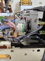
Capstan motor gave acceptable but higher than spec W&F. Replaced with Dual Speed externally adjustable Matsushita motor but the driver circuitry didn't like it, there was a slow oscillation on the 12V motor line in sync with a high W&F sine wave like pattern. Still very good speed stability. A single speed dubious looking Mabuchi EG-530AD-2B came handy resulting to 0.035% WRMS W&F (A.N.T. speed tape). Onkyo service manual Spec is 0.04% WRMS.
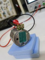
Finally found an MMI-6S series Matsushita NOS motor to replace the new production possibly fake Mabuchi. Which was fine for W&F but running rather hot, also showing bit much of a speed drift cycle over time. The NOS one weighs heavier, runs cooler, fixing the pitch at its back trim is far better predictable. Stays there.
Remote control Onkyo RC-125T was missing. I found one later. A similar Onkyo deck remote was also tried but incompatible.
Test Tapes used:
ABEX, Sony, TEAC, A.N.T. Audio, Hanspeter Roth, FixYourAudio
All service manual adjustment steps successful (manual found in hi-fi engine)
Bias & level internal oscillator test signal adjusted. Tape bias trim by Auto Accubias (micro controller).
I desoldered all NJM4558 & BA15218 from audio signal positions and installed sockets.
Mod op-amps current config:
Q215 NJM5532D Line Amp*
Q217 NE5532 Out Buffer
Q301 uPC4570 HP Amp
Q151 NE5532 In Buffer
Q401 uPC4570 Rec Amp
Q403 BA15218 Rec Head drive Amp
Q201 TC4066BP CMOS switch replaced with MAXIM MAX4066A
*The high slew rate ADA4625-2 tested stable for Q215 as well
Red dots on the annotated schematic are signal path caps replaced with Nichicon FG or ELNA Silmic II and a WIMA. To refresh them. All removed Nichicon VX(M) caps proved good on the LCR though. Factory differences found in the deck vs the schematic like extra coupling cap after the input buffer and a jumper instead of coupling cap to the headphone output also noted. The DIN input is useless nowadays. Its socket's push contacts changing between DIN/RCA routes I bypassed.
Bulb behind cassette came burned out. Replaced with a white LED and limiting resistor. Running it at 20mA is not subtle but I can see the remaining tape run and heads dirt state better in the dark.
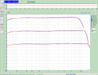
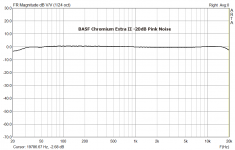
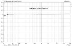
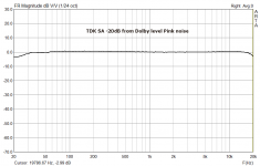
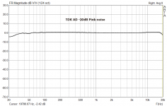
Sine sweeps not valid below 100 Hz due to new sound card without correction file yet. Cross-checked ok in the bass with older card periodic pink noise in REW & ARTA. Sweep levels are actual to 0dB front panel meters reference (its a 200nWB/m ANSI deck). FFT is showing the source loop at Dolby level 1.1V RMS out.
Sound is very good. Was good originally (a well regarded deck in its time) but took a substantial lift after the restoration and mods.
My findings:
251mm L (9.9") or 80mm Diam. capstan motor belt of 5-6mm width seems right. PRB FRW9.7 246mm worked bit better than FRW9.6 244mm. Back tension belt is 25mm Diam. square section, about 1mm wide. Belt it came with was crap and narrow off-riding the pulley. Back tension belt was missing. Found a melted blob behind a flywheel. Should have been its remains.
After cleaning, lubing, new left pinch roller standard practices, mechanical alignment was done with M300 gauge, Sony Mirror Cassette, TEAC Torque cassette.
Measured bias freq ~110kHz
Source loop THD measurement at +5dB red or 2V RMS with original Q221 2SD655F mute 5V VEBO 0.15%. replaced with 2SD1302S 12V VEBO 0.12%
REC/PB ref match at REC CAL level panel pots +0.6dB for RTM FOX C60 Type1. Chosen because new production with a spec sheet.
REC CAL level panel pots range +5/-3dB
Positive notches +1dB each
Negative first two notches -1dB next two -0.5dB last one ineffective
The REC/PB heads combo should be Canon M&X Permalloy
Clutch and reel motors still alright
Capstan motor gave acceptable but higher than spec W&F. Replaced with Dual Speed externally adjustable Matsushita motor but the driver circuitry didn't like it, there was a slow oscillation on the 12V motor line in sync with a high W&F sine wave like pattern. Still very good speed stability. A single speed dubious looking Mabuchi EG-530AD-2B came handy resulting to 0.035% WRMS W&F (A.N.T. speed tape). Onkyo service manual Spec is 0.04% WRMS.
Finally found an MMI-6S series Matsushita NOS motor to replace the new production possibly fake Mabuchi. Which was fine for W&F but running rather hot, also showing bit much of a speed drift cycle over time. The NOS one weighs heavier, runs cooler, fixing the pitch at its back trim is far better predictable. Stays there.
Remote control Onkyo RC-125T was missing. I found one later. A similar Onkyo deck remote was also tried but incompatible.
Test Tapes used:
ABEX, Sony, TEAC, A.N.T. Audio, Hanspeter Roth, FixYourAudio
All service manual adjustment steps successful (manual found in hi-fi engine)
Bias & level internal oscillator test signal adjusted. Tape bias trim by Auto Accubias (micro controller).
I desoldered all NJM4558 & BA15218 from audio signal positions and installed sockets.
Mod op-amps current config:
Q215 NJM5532D Line Amp*
Q217 NE5532 Out Buffer
Q301 uPC4570 HP Amp
Q151 NE5532 In Buffer
Q401 uPC4570 Rec Amp
Q403 BA15218 Rec Head drive Amp
Q201 TC4066BP CMOS switch replaced with MAXIM MAX4066A
*The high slew rate ADA4625-2 tested stable for Q215 as well
Red dots on the annotated schematic are signal path caps replaced with Nichicon FG or ELNA Silmic II and a WIMA. To refresh them. All removed Nichicon VX(M) caps proved good on the LCR though. Factory differences found in the deck vs the schematic like extra coupling cap after the input buffer and a jumper instead of coupling cap to the headphone output also noted. The DIN input is useless nowadays. Its socket's push contacts changing between DIN/RCA routes I bypassed.
Bulb behind cassette came burned out. Replaced with a white LED and limiting resistor. Running it at 20mA is not subtle but I can see the remaining tape run and heads dirt state better in the dark.
Sine sweeps not valid below 100 Hz due to new sound card without correction file yet. Cross-checked ok in the bass with older card periodic pink noise in REW & ARTA. Sweep levels are actual to 0dB front panel meters reference (its a 200nWB/m ANSI deck). FFT is showing the source loop at Dolby level 1.1V RMS out.
Sound is very good. Was good originally (a well regarded deck in its time) but took a substantial lift after the restoration and mods.
Attachments
-
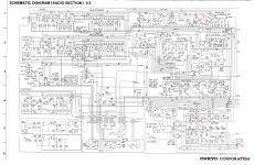 TA-2570 Reworked Schematic Notes.png906.8 KB · Views: 654
 -
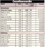 Ranking Audio Mag DE.jpg81.7 KB · Views: 578
 -
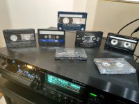
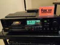 Now Playing after mods.jpg748.8 KB · Views: 661
 -
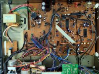 Inside mods.jpg1 MB · Views: 622
 -
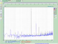 TA-2570 Loop THD 0dB After Mods.png51.5 KB · Views: 697
 -
 Onkyo TDK D Used Sine Sweep.png43.1 KB · Views: 658
 -
 IMG_20190622_002605.jpg253.2 KB · Views: 492
 -
 Matsushita MMI-6H2LWDR.jpg294.4 KB · Views: 532
 -
 Inside mods detail a.jpg281.7 KB · Views: 514
 -
 TA2570_Matsushita_Motor.jpg536.3 KB · Views: 951

The Playback Amp
For the future TA-2570 tweaker bumping into this, here's an interesting section of this deck:
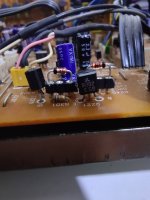
The playback head's signal does not go to a discrete input stage or to an eight pin through hole chip as in most decks. Instead there is a vertically mounted all SMD small daughter board with NJM2068 low noise op-amp and few extra components. Named NHIC-3205 in the manual's parts list or NCHIC3205 on the main pcb.
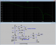
It has resistors and capacitors for feedback, compensation, and partial EQ filtering. External output coupling and feedback to ground electrolytic caps, bias trap adjustable coils (creating 110kHz notch), EQ caps, and playback level pots complete the circuit. There are also two EQ curve switching transistors on this board. One for each channel. They will bypass or engage a voltage divider's shunt leg to switch 70/120uS EQ when receiving high/low state voltage on their bases from the cassette type sensor contacts in the well.
For completeness I attach simulation analysis of the input (PB amp) stage as a whole.
For the future TA-2570 tweaker bumping into this, here's an interesting section of this deck:
The playback head's signal does not go to a discrete input stage or to an eight pin through hole chip as in most decks. Instead there is a vertically mounted all SMD small daughter board with NJM2068 low noise op-amp and few extra components. Named NHIC-3205 in the manual's parts list or NCHIC3205 on the main pcb.
It has resistors and capacitors for feedback, compensation, and partial EQ filtering. External output coupling and feedback to ground electrolytic caps, bias trap adjustable coils (creating 110kHz notch), EQ caps, and playback level pots complete the circuit. There are also two EQ curve switching transistors on this board. One for each channel. They will bypass or engage a voltage divider's shunt leg to switch 70/120uS EQ when receiving high/low state voltage on their bases from the cassette type sensor contacts in the well.
For completeness I attach simulation analysis of the input (PB amp) stage as a whole.
Attachments
A Sony TC-K7 you mean?
I'm sorry, I thought K7 was a universal slang for "cassette". Turns out it's just francophone.
The player I still kept from my teen years is a much more modest one: Technics RS–TR333. Your tweaks and write ups are inspirational.
Ah a dual-well deck. Many had such for easy copying back in the day. All decks are nice for sentimental reasons. I have a friend who collects and I also put hand in his big decks like Nak CR-7 Nak RX-505 Lux K03 Revox B215 etc. etc. but I also like the common man decks we all had or seen around when youngsters. If it was only about hi-fi purity I would run volumio on a raspberry pie instead. No tape can technically match the SINAD championing hundred dollar DACs of today. Reel 2 Reel included. Subjectively tape its still an emotionally moving rainy afternoon hands-on alternative, a glorious classic analog sound. Sometimes bettering vinyl replay even.
Reading and smiling. Very much agree, as many who have ever enjoyed cassettes and decks, I assume.
 Cassettes - better than you don't remember - YouTube
That was a good dose of nostalgia, nodding and useful information. Also looks like dolby S decks are much more affordable now then 5 years ago when the video was created.
Hi Jump
Usual method to directly check or adjust the bias current was a two pins test point for AC VTVM needle meter that could reliably read small voltages in the many kHz. Passing head bias mA through a very small value resistor (like 0.1R) voltage dropping in the 30-40mV region.
But how high AC voltage is created by the bias current in the inductive heads? Lets see on this Onkyo with highest bias IV tape. Well, it can jump quite high. Over 100Vpp (!) across the erase head for metal tape.
Attached: Metal tape bias voltage rec head, erase head.
Attachments
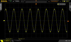
Over 100Vpp (!)

Almost makes me want to buy same deck someday and to go through restoring according to your notes. Although, decks are complex beasts in my eyes. Intrertwining mechanic and electric complexity. So I better be staying out of troubles.
Last edited:
Bias details
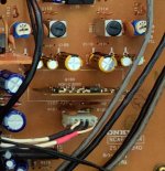
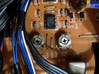
If servicing without many test gear and no verified flat to IEC blank cassettes to can reliably adjust bias by frequency response, just start with valid bias pots positions as mine pictured. Usually found pointing even further to the left in this model i.e. more heavily biased. Like it can be seen in post#1's fourth picture.
Those pots provide base adjustment for Onkyo's Auto Accubias to sit on. Which fine tunes for various tapes when set to rec pause and the START button is pressed. The micro-controller executes a test recording sequence. First tells an NMOS switch to route the CAL oscillator's signal to tape. Then reads it back to level two spot frequencies by varying the bias. Saves to memory, rewinds the tape and the screen displays TUNED. If the system could not manage an odd or worn tape within programmed response tolerances it will still display TUNED but with faint characters. Its a rare cal failure indication. RESET button clears the Accubias memory. Power off does the same.
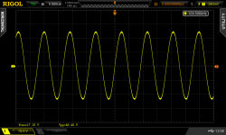
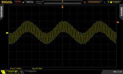
Here's also how the CAL oscillator's test signal should look (probe the TP-5 test pad found on NCAF-3344 vertical board's corner). Its a mix of 400Hz & 12kHz. Should be adjusted for proportion and overall level by two pots on the aforementioned board. Looking for equal thickness below and above the horizontal axis and a total level of 30mVpp.
If servicing without many test gear and no verified flat to IEC blank cassettes to can reliably adjust bias by frequency response, just start with valid bias pots positions as mine pictured. Usually found pointing even further to the left in this model i.e. more heavily biased. Like it can be seen in post#1's fourth picture.
Those pots provide base adjustment for Onkyo's Auto Accubias to sit on. Which fine tunes for various tapes when set to rec pause and the START button is pressed. The micro-controller executes a test recording sequence. First tells an NMOS switch to route the CAL oscillator's signal to tape. Then reads it back to level two spot frequencies by varying the bias. Saves to memory, rewinds the tape and the screen displays TUNED. If the system could not manage an odd or worn tape within programmed response tolerances it will still display TUNED but with faint characters. Its a rare cal failure indication. RESET button clears the Accubias memory. Power off does the same.
Here's also how the CAL oscillator's test signal should look (probe the TP-5 test pad found on NCAF-3344 vertical board's corner). Its a mix of 400Hz & 12kHz. Should be adjusted for proportion and overall level by two pots on the aforementioned board. Looking for equal thickness below and above the horizontal axis and a total level of 30mVpp.
Attachments
Looks great, I'm taking a vacation from cassette recorders.. LOL Nice project. My feeling about the ADA4625 series part has changed, I know I espoused them in the past but am thinking of replacement with OPA1642, yes I know it is about 3dB noisier.. What is your thought on this?
- Home
- Source & Line
- Analogue Source
- ONKYO TA-2570 cassette deck restoration & mods