This series of diodes are known as the suicide diodes, which destroy the Sony V-fet amplifiers.I replaced it with two 1N4148 diodes as recommended in more than one thread in internet.
Here it is a VD1222, with the V-fets it is the VD1221M.
So it seems. Do they need to be thermally coupled to the heatsink/output transistors?This series of diodes are known as the suicide diodes,
The bias topology is different, so I would stick to the original setup, bonding the 2x1N4148's to the power transistors.
But that very inside bonding (of the two diodes) of these VD-diodes proofed unreliable!
There's a lot of solder paste in the pictures - better remove with ipa & old toothbrush (shining second life!).
But that very inside bonding (of the two diodes) of these VD-diodes proofed unreliable!
There's a lot of solder paste in the pictures - better remove with ipa & old toothbrush (shining second life!).
It is flux from the standard solder wire - do you think it can create technical (other than visual) problems?There's a lot of solder paste in the pictures
Hmm... some of these can, depends. Better have it removed. Problems arise when organic/carbon elements are involved. It's sticky too, attracks other contaminations, conductive maybe.it can create technical problems?
I prefer surgery conditions on board: IPA.
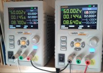
OK, powered the channel up (from power supplies) - nice and slowly starting from 40V gradually increasing to nominal 60V.
Seems stable, idle current is adjustable.
Screenshots ar from state of 10mV across emitter resistors.
Time to tidy it up and see what happens when powering from its main supply.
Seems stable, idle current is adjustable.
Screenshots ar from state of 10mV across emitter resistors.
Time to tidy it up and see what happens when powering from its main supply.
Attachments

Ok, tested the rectifier and main capacitors under power - everything seems ok.
Connected the main capacitors to the amplifier board (rails) - and the channel output sits on a rail.
No smoke though.
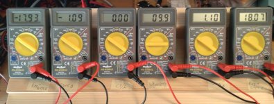
After some quick measurements (when powering the amp for some seconds at a time) it surfaced the -18V of regulated power is missing:
https://www.diyaudio.com/community/threads/onkyo-m-5030-burnt-channel-rebuild.408391/post-7581007
Probably 2SK246 (Q423) is open (zener D408 both ends have the same potential).
Bridging Q423+D408 combo with 4k7 resistor (as has been done also in other Onkyo models) brought back the negative voltage and also the output voltage returned to zero (speaker relay activates now normally).
B1 is +/-60V, 2SK246 is 50V by datasheet - should I replace (as precaution) also the other ones in the similar function i.e. is it a disaster waiting to happen?
There is also a thread on similar topic in the forum:
https://www.diyaudio.com/community/threads/2sk246-replacement-as-constant-current-device.342280/
Connected the main capacitors to the amplifier board (rails) - and the channel output sits on a rail.
No smoke though.
After some quick measurements (when powering the amp for some seconds at a time) it surfaced the -18V of regulated power is missing:
https://www.diyaudio.com/community/threads/onkyo-m-5030-burnt-channel-rebuild.408391/post-7581007
Probably 2SK246 (Q423) is open (zener D408 both ends have the same potential).
Bridging Q423+D408 combo with 4k7 resistor (as has been done also in other Onkyo models) brought back the negative voltage and also the output voltage returned to zero (speaker relay activates now normally).
B1 is +/-60V, 2SK246 is 50V by datasheet - should I replace (as precaution) also the other ones in the similar function i.e. is it a disaster waiting to happen?
There is also a thread on similar topic in the forum:
https://www.diyaudio.com/community/threads/2sk246-replacement-as-constant-current-device.342280/
- Home
- Amplifiers
- Solid State
- Onkyo M-5030 burnt channel rebuild