Very good points!
I have measured actually the Op Amps voltage with my multimeter and when i saw that they were operating at +/-5V i asked myself: why they did that?
Actually the NJM4560D are rated for +/-18V max and +/-15V typical as you guys said.
Well, I'll try a couple other op amps with that voltage (all the op amps I have in mind to try work with +/-5V too although their typical voltage is +/-15V),
and see how it sounds and take it from there ...
EDIT:
Now i have to figure out how to work underside that board, there are hardwired connections (flat cables) going from the display to the main board and hardwired
connections too (what i think it is) of the headphones output PCB to the main board as well. So, really difficult to remove the entire board unless I somehow disassemble everything... :/
Tricky thing... I guess I will need to work in a very tight space...
Last edited:
Why did they do that - probably because 6.3V capacitors are cheaper than 16V and 25V ones 😉
LOL true 😀 😀 😀
Sony also do the same in a lot of players and run the analogue stages on -/+5 volts. The maximum output swing is generally 2 volts rms and so a -/+5 volt rail easily covers the requirement. The other way of looking at it is to say it is actually a good engineering decision providing the required specs can be met.
As to working on the player, it is probably only five minutes work to strip the machine right down to a bare chassis. Remove the front, unscrew everything in sight and pull it apart.
As to working on the player, it is probably only five minutes work to strip the machine right down to a bare chassis. Remove the front, unscrew everything in sight and pull it apart.
Now i have to figure out how to work underside that board, there are hardwired connections (flat cables) going from the display to the main board and hardwired
connections too (what i think it is) of the headphones output PCB to the main board as well. So, really difficult to remove the entire board unless I somehow disassemble everything...
The cables from the disc drive can be unplugged.
The front panel boards will probably remain with the main board - this makes board handling a bit clumsier (unless you decide to unsolder them - doable, just takes some effort).
The wires from the mains transformer I would just unwind/cut and solder them back later during assembly.
In order to work on it decently you have to get the board on your table.
CD Player opened up, NJM4560s removed, DIP-8 sockets are in place...
...
Storyline
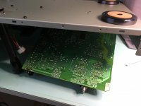
Photo 1: Plato,the Greek Philosopher, said "necessity is the mother of invention" :
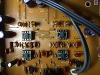
I have released the boards from all of its screws, unplugged CD transport cables from main board, removed back panel (which holds the RCA connectors etc.) and voila, turned the player upside down while keeping the case at a certain height and let the main board slip down enough for me to work on the Op Amps. The other side of the board is still connected to the display, no issues.
Marked in yellow rectangles are the op amps to be removed.
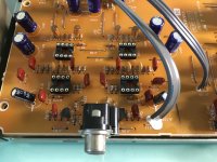
Photo 2: DIP-8 sockets in place!
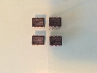
Photo 3: these 4 guys had to be removed, sorry.
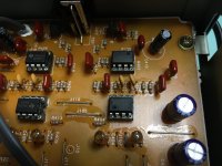
Photo 4: NE5532 in for the first listening tests until Mouser order gets delivered. I haven't put decoupling capacitors at terminals 4 and 8 yet as they are part of the order as well.
But let's see what i get from these... Maybe it's gonna be an "oscillation" party this evening, who knows, maybe not...
P.S. unfortunately I currently have only 2 opa2134 otherwise I'd put them in first...
but!
I have 4 AD823s in addition to the NE5532s 😀 What do you think?
...
Storyline
Photo 1: Plato,the Greek Philosopher, said "necessity is the mother of invention" :
I have released the boards from all of its screws, unplugged CD transport cables from main board, removed back panel (which holds the RCA connectors etc.) and voila, turned the player upside down while keeping the case at a certain height and let the main board slip down enough for me to work on the Op Amps. The other side of the board is still connected to the display, no issues.
Marked in yellow rectangles are the op amps to be removed.
Photo 2: DIP-8 sockets in place!
Photo 3: these 4 guys had to be removed, sorry.
Photo 4: NE5532 in for the first listening tests until Mouser order gets delivered. I haven't put decoupling capacitors at terminals 4 and 8 yet as they are part of the order as well.
But let's see what i get from these... Maybe it's gonna be an "oscillation" party this evening, who knows, maybe not...
P.S. unfortunately I currently have only 2 opa2134 otherwise I'd put them in first...
but!
I have 4 AD823s in addition to the NE5532s 😀 What do you think?
Attachments
Any intention for changing the signal lytics (C219/220) for film ones?
And how much dc is on the output pin of the output opamps?
And how much dc is on the output pin of the output opamps?
Try the AD823's. They should work well at the lower supply voltages used.
The circuit shows that L and R channels randomly swap between IC packages (which I think could be drawn incorrectly) but even so there is nothing to stop you having different types in different locations.
Try the OPA's for Q401 and Q402 which are used as the first stage of the analogue stages.
The circuit shows that L and R channels randomly swap between IC packages (which I think could be drawn incorrectly) but even so there is nothing to stop you having different types in different locations.
Try the OPA's for Q401 and Q402 which are used as the first stage of the analogue stages.
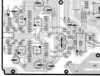
The "opamp swap" is a mistake in the dawn diagram - look at the board layout screenshot in post #2, the IC-s stay well in the proper channel.
I wondered about the same thing and therefore posted also the board layout.
I wondered about the same thing and therefore posted also the board layout.
hi guys,
a quick update: NE5532 sound is way better in every aspect compared to the original NJMs that were inside.
I don't like to review Op Amps without letting readers know what the rest of my system is:
So, I play this Onkyo CDP through an Exposure 2010 amplifier which drives a pair of Monitor Audio Silver 200 floorstanders.
I use StraightWire Sextet speaker wires in a bi-wiring configuration.
I use custom interconnects I build by myself using Mogami low capacitance cable and Neutrik REAN NYS373-* connectors.
With that said, putting the NE5532s in there is like I'm listening to a totally different player (in a good way). More soon as I want to listen to other OP Amps too...
1. I can't find C219, C220 named capacitors in the circuit? Are you sure the capacitor numbers are spelled correctly? (I'm wearing eyeglasses though, maybe my sight plays games with me...)
2. You mean the pins 1 and 7 i guess?
Mooly, please, which are the first stage and which are the second stage Op Amps in this case?
Also,
Do i really need coupling (bypass) 0.1uf capacitors in this CDP?
I was studying the schematics of the Marantz CD63 in that CD 63 mods thread, and I don't see Marantz having such coupling capacitors at pins 4 and 8 of the Op Amps (so maybe it makes sense to add it?) ,
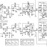
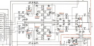
But when I look at this Onkyo DX-710 schematics I can see 0.1uF caps connected at pins 4 and 8 (in some weird configuration though but as you said maybe there is an error in the schematics itself ?).
Am I getting something wrong ?
Attached photos of the Marantz CD63 schematics (photo 1) and of this Onkyo schematics (Photo 2 and 3).
a quick update: NE5532 sound is way better in every aspect compared to the original NJMs that were inside.
I don't like to review Op Amps without letting readers know what the rest of my system is:
So, I play this Onkyo CDP through an Exposure 2010 amplifier which drives a pair of Monitor Audio Silver 200 floorstanders.
I use StraightWire Sextet speaker wires in a bi-wiring configuration.
I use custom interconnects I build by myself using Mogami low capacitance cable and Neutrik REAN NYS373-* connectors.
With that said, putting the NE5532s in there is like I'm listening to a totally different player (in a good way). More soon as I want to listen to other OP Amps too...
Any intention for changing the signal lytics (C219/220) for film ones?
And how much dc is on the output pin of the output opamps?
1. I can't find C219, C220 named capacitors in the circuit? Are you sure the capacitor numbers are spelled correctly? (I'm wearing eyeglasses though, maybe my sight plays games with me...)
2. You mean the pins 1 and 7 i guess?
Try the AD823's. They should work well at the lower supply voltages used.
The circuit shows that L and R channels randomly swap between IC packages (which I think could be drawn incorrectly) but even so there is nothing to stop you having different types in different locations.
Try the OPA's for Q401 and Q402 which are used as the first stage of the analogue stages.
Mooly, please, which are the first stage and which are the second stage Op Amps in this case?
Also,
Do i really need coupling (bypass) 0.1uf capacitors in this CDP?
I was studying the schematics of the Marantz CD63 in that CD 63 mods thread, and I don't see Marantz having such coupling capacitors at pins 4 and 8 of the Op Amps (so maybe it makes sense to add it?) ,
But when I look at this Onkyo DX-710 schematics I can see 0.1uF caps connected at pins 4 and 8 (in some weird configuration though but as you said maybe there is an error in the schematics itself ?).
Am I getting something wrong ?
Attached photos of the Marantz CD63 schematics (photo 1) and of this Onkyo schematics (Photo 2 and 3).
Attachments
Hello,
As long as you have it open and working on the board, would replace C419 & C420 (the DC output blocking caps) with larger, bi polar caps.
Going to larger values, bipolar and possibly higher voltage rating makes any distortion these caps add taken down to pretty much the edge of being capable to measure any at all.
Replaced mine with 220uf/35 volt Panasonic bipolar caps and it seems to me to have helped especially with the low bass. FWIW as I didn't have a non modded one to compare it with afterward. Anyway, pretty easy to do and cheap as well.
Regards,
Greg
1. I can't find C219, C220 named capacitors in the circuit? Are you sure the capacitor numbers are spelled correctly? (I'm wearing eyeglasses though, maybe my sight plays games with me...)
Yes, my mistake - output caps are C419/420. 😱
Do i really need coupling (bypass) 0.1uf capacitors in this CDP?
I was studying the schematics of the Marantz CD63 in that CD 63 mods thread, and I don't see Marantz having such coupling capacitors at pins 4 and 8 of the Op Amps (so maybe it makes sense to add it?) ...
Back in the "old days" the opamps were "slower" and there was less RFI "in the air" (and less noise in the power lines) - consider this as routine hygiene - just do it and do not bother your head about it any more. 😉
Otherwise you may run into unexpected problems in case of some unfavourable conditions.
Last edited:
Mooly, please, which are the first stage and which are the second stage Op Amps in this case?
On the PCB layout they are Q401 and Q402.
Great thank you all! got it.
I will work again on the board for adding the opamp 0.1uF coupling capacitors so I will look onto those C419,C420 as well.
@Mooly,will try the combination of opamps you suggested too 🙂
I will work again on the board for adding the opamp 0.1uF coupling capacitors so I will look onto those C419,C420 as well.
@Mooly,will try the combination of opamps you suggested too 🙂
...output caps are C419/420
And how much dc is on the output pin of the output opamps?
Hi Madis,
About the output caps, it looks like film capacitors at 22uF are really big...
Talking about 35-40mm width...
Could I get away with good bipolar electrolytics (nichicon muse maybe) as
starkeyg advised?
To your other question, I have checked the DC voltages and this is what i found (should I worry about the results?)
With NE5532 in:
Q401 - OnSemi NE5532
pin 1: -0.125V
pin 7: -0.138V
Q402 - OnSemi NE5532
pin 1: -0.125V
pin 7: -0.138V
Q403 - Texas Instruments NE5532
pin 1: -0.233V
pin 7: -0.138V
Q404 - Texas Instruments NE5532
pin 1: -0.124V
pin 7: -0.213V
measured 3 times to ensure i was getting correct readings...
P.S. I have tried to put AD8599 but it didn't like it...only left channel was playing. Removed it until i install coupling caps..
Attachments
Last edited:
If one channel worked and one did not then I would suspect something went amiss somewhere rather than the opamp not being suitable.
About the output caps, it looks like film capacitors at 22uF are really big...
Talking about 35-40mm width...
Could I get away with good bipolar electrolytics (nichicon muse maybe) as
starkeyg advised?
You do not actually need 22uF there to steer the next amplifier's input stage - the lytics are placed in places like this intentionally oversized to reduce their distortion.
I have usually replaced them in similar places with 2.2...4.7 Wima MKS2 film capacitors. They do not cost much and in the same size range go up to 10uF.
If you want to visualize the effect of the output capacitor on the frequency response then the easiest way is to use RMAA (RightMark Audio Analyzer).
If you are willing to separate also the power rails for left and right channels (requires invasive techniques) then you can observe also change in channel separation and improvement of clarity.
If you want to play around with the output caps without further hassle then you can solder sockets to the board and plug the caps in to your liking. Whatever is chosen can be soldered in from above (without taking out the board).
- Home
- Source & Line
- Digital Source
- Onkyo DX710 Op Amp mods asking advice