Hey everyone, I need some help with my Onkyo A-10. I just finished a recap on it. I replaced all electrolytic's in the amp including the filter caps. I have the service manual and have double checked myself multiple times to make sure all caps replaced correctly. I just hope I didn't do a dumb move and ruin anything. I'm still learning so don't hold back.
The problem I have is the main filter caps. After I had finished the recap I did my usual checks to make sure no wires are broken, no components shorting, no DC at the outputs and adjust bias after 30 mins. All was great. DC at the outputs showed 15 MV after warm-up for both channels. Bias current was right according to the service manual ( adjusted to 35mv, manual calls for 40mv). All was well. No unusual noise nothing but great sound. After about 2 hours I'm guessing, I hear a loud POP!!! Which scared the hell out of me and I look over at the amp and smoke is just pouring out of the top of the vents, like crazy! So I run over and rip the cord out of the wall. I opened the amp up to find one of the left channel filter caps had bulged and caused some guts to be spilled out from it. It's not shorted luckily but definitely damaged and the cause of the pop and smoke.
After incident checks, I have done is; rectifying diode board checks good. No shorts whats so ever on any diodes. No solder bridges anywhere. No shorts from and components, including leads or post I might have bent, nothing I can see. I have checked a few diodes in the protection circuit but need to check more after I get the face plate off.
My main question right off the bat is, did I do a dumb move and wire the filter caps wrong? This amp was my first time dealing with a 2 section cap (dual 13,000uf).
I appreciate everyone's time in advance.
Hi Bob,
Getting the filter capacitors backwards could do it, but I would think that you would have had the blow up soon after turning the amp on in that case.
If you have a variac (variable AC transformer), use that to allow only a small voltage on the main filter capacitors and measure this with respect to the chassis. Confirm that the capacitors are in the right way.
One thing that can cause a delayed blow up would be excessive current draw. Normally the only things that can cause that are an amplifier section, a voltage regulator or a shorted or leaky rectifier diode. It must be something basic like this.
-Chris
Usually if in the wrong way around they will complain pretty soon after turning on.
Could be an issue with incorrect wiring or just a faulty capacitor.
Could be an issue with incorrect wiring or just a faulty capacitor.
That's what I was thinking as well. It played for a long time with no issues? Wow thanks, guys for the quick replies. I don't have a variac, but I can borrow one, Ill ask.
Last edited:
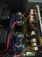
For the negative section, the positive of the capacitor goes to ground and the negative goes to the rectifiers and amplifier supply.
-Chris
-Chris
Okay, just to clarify are you saying the cap with the red lead on it going to positive needs to be switched around, so that red wires go to negative and the positive of that cap goes to the negative of the others cap, like in series?
Looks like the red wires are positive, the black wires are negative, and the blue wires are ground, is this correct? In other words the red wires go to the + on the bridge rectifier, the black wires go to the - on the bridge rectifier, and the blue wires go to chassis ground, is this correct? Both capacitors with black wires need to be reversed AND REPLACED, + to the copper buss bar.
Craig
Craig
Don't pay much attention to me but I would wire each positive capacitor terminal with one red wire and both black wires per transformer to the copper link between both negative capacitor terminals and use the lift resistors for blue wires, unless you see the blue wires going to transformer 🙂
Yah all 4 filter caps are getting thrown away and replaced. I'm also going to replace all diodes on the rectifying circuit as well just for safe measure, diodes aren't that expensive anyways. I'm praying that nothing else got damaged although with that dramatic failure I would be surprised if nothing else was damaged.
From my understanding is the red wires are the B+ and the blue wires are the B- leaving the black wires for ground. It looks od there going to ground I see, but the original filter cap has that orientation? I don't have a before pic but Ill post a pic from Google.
From my understanding is the red wires are the B+ and the blue wires are the B- leaving the black wires for ground. It looks od there going to ground I see, but the original filter cap has that orientation? I don't have a before pic but Ill post a pic from Google.
Attachments

Don't pay much attention to me but I would wire each positive capacitor terminal with one red wire and both black wires per transformer to the copper link between both negative capacitor terminals and use the lift resistors for blue wires, unless you see the blue wires going to transformer 🙂
I think I see what you're saying.
Which is ground blue or black, looking at the latest picture I would say black is ground, red is + and blue is -.
Craig
Craig
If it's possible take some original-like chassis-mount caps. I've taken the 22mF/80V-Nichicon NT (bypassed by 100nF CDE WPP/WMF each) for my last A-5/A-7 and A-10 restaurations. Working fine, fits like original ones. You could get them at Digikey/Mouser.
Also look for the larger valued 3W resistor in the power supply section, replace it with a 5W type if not done yet and lift it a little bit from the board. It is baking the smaller caps near by. If you want to you could also replace the Zener-based and cap-bypassed supply for the smaller voltages in the inputstage by more quiet alternatives. Maybe you could take a look at the small ceramic-caps (9 & 5pf if I'm not wrong) on the amplifier-boards. In some amps I had on my table they were mechanical broken (cracked case). I replaced them by silver-micas. If yours got the 3,3µF-electrolyt-caps near the outputs you could also replace them by MKT-types for a longer lifespan.
Sometimes the glue used to fix the "bigger" caps on the ampfifier-board caused some defective legs of resistors - check for it.
I'm very surprised you got two hours out of it before it let the smoke out. There shouldn't be any problems past the filter caps, replace the diodes and the four capacitors and you should be good to go. The black wires will go to the copper buss bars, reds will go to the + terminals and the blues will go to the - terminals.
Craig
Craig
Same here, I can't really wrap my mind around this at all and the fact that it was working for that long makes no sense. It will be good to let this amp sit a while I order parts for it so I can clear my head a bit.
So if I understand you correctly llwhtt your saying the cap with the black wire connected to it needs to be switched, as in the black wire goes to - then the + post from that cap goes to the - of the other cap with the red wire going to the + and the blue wire going between the + and - of the too caps. I'm going to try to draw it out and post it so it's clear.
I'll look into that nfsgame.
Hi Bob,
I think you've got it straight now. Just take your time connecting it up again when you do. Like Craig said, the damage should be limited to the capacitors, possibly rectifier diodes and your pride.
Years ago a well known manufacturer did something similar on a line of receivers. This was from the factory. "Fix it in the field".
-Chris
- Home
- Amplifiers
- Solid State
- Onkyo A-10 Help needed!