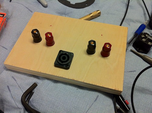
Rear panel progressing. Need to find some RCA jacks that will work for the wood panel. The ones I have require some hogging out of the panel and won't leave much meat behind. Might machine a sub-plate instead if I can't find a suitable jack. There are some neutrik ones that will work but I won't pay for shipping for such a small order since I'm a cheap ***. So, a sub-plate may be the solution...
Still trying to figure out how I'm going to test the channels independently. I may end up with a couple connectors... I have some of the larger molex connectors that would work fine. In retrospect, a couple terminal blocks on the PSU PCB may have been a good idea. Ah, hindsight.
Still trying to figure out how I'm going to test the channels independently. I may end up with a couple connectors... I have some of the larger molex connectors that would work fine. In retrospect, a couple terminal blocks on the PSU PCB may have been a good idea. Ah, hindsight.
Nice tread
My 2 C about the imputs
Why not XLR they are there if you going to make balanced one and work fine for mono
Neutrik barrel type will fit nicely troug back pannel
My 2 C about the imputs
Why not XLR they are there if you going to make balanced one and work fine for mono
Neutrik barrel type will fit nicely troug back pannel
Might machine a sub-plate instead if I can't find a suitable jack.
Probably a good idea. The wood looks nice, BTW.
Also, convention says that you put the black (grounds) of the speaker output posts in the center, so they are mirror-imaged.
Still trying to figure out how I'm going to test the channels independently.
Unsolder the amp board's power wires at the PSU. Test the PSU. Re-solder one channel, test, bias. Re-solder the other one, test, bias. Then set final bias. Done!
Last edited:
I was wondering how that should work... makes sense given the grounds will go back to the PSU PCB in the middle of the chassis anyway.
PSU is tested and reads 24.3V +/- on both sides so good to go there. I guess I can test one side independently and assuming that's fine, go ahead and test the other one without disconnecting the first.
Also, I got my bulb tester wired up with a little clip on lamp that has been sitting unused for years. Yet another piece of "scrap" used for this project! Does it matter what wattage bulb to use? I tested it with just the PSU and as expected, it lit up briefly.
Also, convention says that you put the black (grounds) of the speaker output posts in the center, so they are mirror-imaged.
PSU is tested and reads 24.3V +/- on both sides so good to go there. I guess I can test one side independently and assuming that's fine, go ahead and test the other one without disconnecting the first.
Unsolder the amp board's power wires at the PSU. Test the PSU. Re-solder one channel, test, bias. Re-solder the other one, test, bias. Then set final bias. Done!
Also, I got my bulb tester wired up with a little clip on lamp that has been sitting unused for years. Yet another piece of "scrap" used for this project! Does it matter what wattage bulb to use? I tested it with just the PSU and as expected, it lit up briefly.
If you use a 100w bulb (incandescent) it should limit the AC if there is a major problem.
Did you test the PSU voltage in the amp case as well?
Did you test the PSU voltage in the amp case as well?
Yup, tested the PSU in the amp case as well. Decided to use the thermistor as part of the PCB as well for simplicity sake if nothing else.
If you use a 100w bulb (incandescent) it should limit the AC if there is a major problem.
Did you test the PSU voltage in the amp case as well?
Great! Hook up one of the amp channels. Turn it on with the bulbtester. If the glow is similar to what you saw with the PSU, then disconnect the bulbtester and power it up. Bias to .5v and zero offset.
Lather, rinse, repeat with the other side.
Lather, rinse, repeat with the other side.
hee the way i did it. fire up the PSU's. connect one amp. adjust bias and offset to little over half my goal. let it warm up. adjust to final setting. wire up next amp and adjust that one while the first amp played on a test speaker.
PS: don't bother with 0V offfset. you will need to readjust after a while anyway.
PS: don't bother with 0V offfset. you will need to readjust after a while anyway.
Last edited:
BTW, for whatever reason, the rising resistance thing went away when I disassembled the pieces and re-measured. They now are at 0 ohms. For the record, I put them in backwards as evidenced by the fact that I had to turn them fully CW to get the reading to zero.
Yes, Bourns. The confusion is whether I installed backwards or not.
Weird. When I measure across the resistors, the values slowly rise till I get an open circuit. Is that a problem with my cheapo DMM?
PS: don't bother with 0V offfset. you will need to readjust after a while anyway.
Yes and no.
Do bother with the zero offset, because if you don't you will not know if you have enough resistance in your bias circuit. For every .1v of bias, make sure the offset is zeroed. Bias more, adjust offset to zero, bias more, zero, etc...
Yes, you will have to go back and do a final adjust to it. Most certainly.
Actually you will need to do it at least twice! 🙂 🙂 🙂
Question - how many meters do you have?
i see what you meen. you don't want to have 0.4V offset. but if you get 20mV just leave it there.
at least twice 🙂 over a period of 2-3 weeks 🙂
i used 2 meters. but 3 will make you stay more sane 😀
at least twice 🙂 over a period of 2-3 weeks 🙂
i used 2 meters. but 3 will make you stay more sane 😀
I had just one $5 DMM as my one and only for the last five years or so. As a matter of fact, it came as part of the minimax headphone amp kit that I bought from beezar as one of my first diy projects. Then I bought two more $5 ones for this project. Then I thought maybe I should invest in a "real" DMM and somehow ended up with a rigol oscilloscope. 😱
I think the three cheapo DMMs will work best in this scenario though. I will use the scope to look for PSU ripple once everything is done. Or maybe track if/how the dc offset and bias change with time since it does have some data logging.
In the meantime, still trying to decide if I should get a real DMM or not!
i see what you meen. you don't want to have 0.4V offset. but if you get 20mV just leave it there.
at least twice 🙂 over a period of 2-3 weeks 🙂
i used 2 meters. but 3 will make you stay more sane 😀
cheap or not cheap
that's matter of trust and repeatability of measurements
for that , you always need to have one trustworthy as etalon
that can be tiresome , if you are working a lot
if not - use what you have ...........
that's matter of trust and repeatability of measurements
for that , you always need to have one trustworthy as etalon
that can be tiresome , if you are working a lot
if not - use what you have ...........
At the very least, I plan on "calibrating" my DMMs to my oscilloscope. Just to make sure they're not grossly inaccurate.
RCA mount on thick panel
Nice build. Especially like the letters! 😀
How to do RCAs on thick panels. See image.
You can counter bore the back or mill it, etc... router in your case in the event that you don't want to be recessed the entire thickness...
I often mount them on Teflon, these are on polycarbonate...
Nice build. Especially like the letters! 😀
How to do RCAs on thick panels. See image.
You can counter bore the back or mill it, etc... router in your case in the event that you don't want to be recessed the entire thickness...
I often mount them on Teflon, these are on polycarbonate...
Attachments
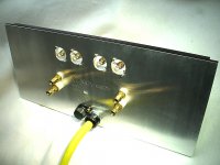
Thanks. Nice panel! I got some RCAs where the threaded portion is a little longer so I think I might be able to get away with just a recess vs. mounting separately. Worst case, if the wood fails, I can redo it with a piece of aluminum or whatever I have lying around.
Nice build. Especially like the letters! 😀
How to do RCAs on thick panels. See image.
You can counter bore the back or mill it, etc... router in your case in the event that you don't want to be recessed the entire thickness...
I often mount them on Teflon, these are on polycarbonate...
When you say similar, you mean it should go on briefly and then go off? If so, then I have a problem somewhere. The light stays on. Does that mean I have a short somewhere? And if so, any guidance on where to start? If not, then I can move forward.
Great! Hook up one of the amp channels. Turn it on with the bulbtester. If the glow is similar to what you saw with the PSU, then disconnect the bulbtester and power it up. Bias to .5v and zero offset.
Lather, rinse, repeat with the other side.
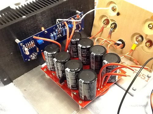
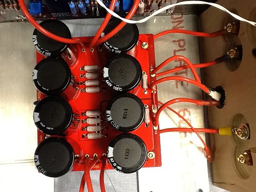
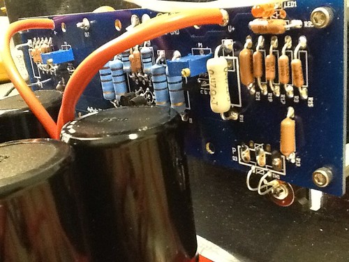
Doh! I thought as much. Where do I start? Seems like such a straight forward PCB. Any typical problems? Here are some pics:

if the light goes off, you are good to go 🙂 if it stays on, there is a problem.
- Status
- Not open for further replies.
- Home
- Amplifiers
- Pass Labs
- oneplustwo F5 build thread