arnoldc
http://www.the-planet.org/images/407a.jpg
Here's the schametic from Gary Kaufman's page. How does this compare to yours?
-- josé k.
http://www.the-planet.org/images/407a.jpg
Here's the schametic from Gary Kaufman's page. How does this compare to yours?
-- josé k.
Your link went 404/forbidden, but I'll elaborate on what I used:
I used the exact power supply from post 34 of this thread,
with the exception of a 250 VCT transformer from Allied, and a 5H 132 ohm choke from Angela (Hammond). I used two 10 ohm 5 watt resistors and two .01 uF 600v orange drop caps for the pre-rectified stage, and in parallel to the choke I used that white 1.0uF non-electrolytic cap which I got from Allied too (hard to find) in addition to the two diodes, two 100uF 450 electrolytics.
I'm getting 180vdc on the main rail end, not 300 (see my comment below)
The main circuit is exactly this:
http://www.angelfire.com/electronic/funwithtubes/Amp-Gain_Block.html
with the exception that I used a .022 uF cap coming from the pot to the first grid (per his verbal writeup), a .0047 cap from the first plate to the second grid (instead of a .022), and a 10K 1 watt resistor for Rk (instead of the 22k - - slightly more gain)
I'm going to drop the value of the 33k resistor at the very top right,
since my voltage is low, maybe will try 10k, as the tube can handle 250v, do you have any suggestions here, can I eliminate it altogether in my case?
Remember of course that I'm using two 6AV6's instead of a 12AX7, the pins are completely different, but the performance is identical.
Actually the 6AV6's have two tiny diodes which I ignore.
The filaments are pins 3&4, the grid is pin 1, cathode pin 2, and plate pin 7. Don't connect anything to pins 5 & 6.
Actually the 6AV6's have two tiny diodes which I ignore.
The filaments are pins 3&4, the grid is pin 1, cathode pin 2, and plate pin 7. Don't connect anything to pins 5 & 6.
As far as the hum goes, you can probably reduce it a little more by lifting the filament reference to about 30v. If you have 180V at the supply, connect something like a 150k in series with a 30k resistor from B+ to ground. Instead of connecting the filament to ground, connect it to the junction between the resistors, and add a bypass cap to ground of 10-100uF.
What's the voltage at your plates? If it's around 100V or so, I wouldn't necessarily increase it. Sure, the tube can take more, but that doesn't mean it will sound better, and by reducing the power supply resistor, you'll increase the ripple at the plate. On the other hand, easy to try and see.
Sheldon
frank754 said:OK, I've finished it and it works, the only thing is that there is considerable AC hum so far. Here is a shot of the underside:
Looks good. As for the hum, what are you using as a power indicator? If that is a neon lamp, it could be the culprit. Try disconnecting it and see if that helps.
Interesting approach about the "reference" above ground for the filament supply, I'd seen it done on plans, but that really informs me more of the procedure.
As far as the HV goes, I eliminated (bypassed) the 330k resistor from the rail, and now I'm getting 175+v on the plates, slightly stronger, but no noticeable loss in quality.
As I mentioned, I added a 100 ohm resistor from one side of the filament supply, just as a wild guess, and 95% of the hum is gone, in fact there is slightly more hum coming from the Fred Nachbauer miniblock-II (two 13EM7's in PP at 3.5 watts) that I'm feeding the pre-amp into, than the pre-amp itself.
The pilot light in parallel with the two tube filaments is just an old-fashioned GE47 bulb.
Hi José,korneluk said:arnoldc
http://www.the-planet.org/images/407a.jpg
Here's the schametic from Gary Kaufman's page. How does this compare to yours?
-- josé k.
I emailed you the schematic.
Well, as far as my version goes of the preamp, I did try a few things and finally it seems I have virtually un-noticeable hum now, if my ear is more than 2' away from the speaker, and even closer it's fairly low.
The pre-amp has two stages, I used 2 6AV6's, and from the cathode of the second one, which has a lower resistance in reference to ground (just 680 ohms) and also a 470uF electrolytic cap to ground, I ran two 100 ohm resistors from this point to each of the two sides of the 6.3v filament supply (which has no center tap), and this seems to have provided the best results yet.
The pre-amp has two stages, I used 2 6AV6's, and from the cathode of the second one, which has a lower resistance in reference to ground (just 680 ohms) and also a 470uF electrolytic cap to ground, I ran two 100 ohm resistors from this point to each of the two sides of the 6.3v filament supply (which has no center tap), and this seems to have provided the best results yet.
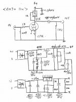
Thanks, I also finally got to making a schematic for exactly what I'm using now. With the turntable, I needed to add a 3-prong grounded cord to get rid of hum almost entirely, plus I redesigned the voltage-divider-based, hum-reducing filament circuit so that it seems optimal now. Running from a CD deck it seems as quiet as a rock.
I based it on the Max Robinson design, as mentioned, but used two 6AV6's, and added a few tweaks. I only have 125vdc and 75vdc on the plates, respectively, and it's not super powerful, but does the job well, in my opinion, so far. I don't think I need to push the voltages any higher for more output, but opinions are welcome.
It can be built for only around $85 or so, with all new parts.
I made the drawing using Open Office Draw and the symbols from here:
http://library.thinkquest.org/10784/circuit_symbols.html
which I kept in a background browser window, and saved the ones I needed one by one, then resized/flipped/etc. the ones I used as images. Seems to be a good "draw" app, for free, hard to line things up at times, but I'm new at it, in the past I did everything by hand. So here's the schematic:
(every time I try to attach something, it seems my images are a bit too large, in the future I'll try, but didn't want to cut any detail from this one)
Were it me, I would probably place the pot in btween the stages, because you can use your guitar volume on the first stage. I would get rid of the NFB in a guitar preamp... ( the 220k resistor running from the output to the cathode of the first tube)
do 1.5k on the first cathode and add a .68 uf cap...and replace the .0047 cap with a .047, or your bass will be very limited.
look up ax84's high octane or P1 for some similar schematics . Also note that some of the old kay/harmony/silvertone line operated amps used a 12av6 as a preamp.
do 1.5k on the first cathode and add a .68 uf cap...and replace the .0047 cap with a .047, or your bass will be very limited.
look up ax84's high octane or P1 for some similar schematics . Also note that some of the old kay/harmony/silvertone line operated amps used a 12av6 as a preamp.
Thanks Dude, I made a note of those mods for guitar amp use as this question comes up too. It seems well suited for hi-fi the original way.
What effect would the .68 uF cap have in parallel with a 1.5k resistor at the first cathode?
Anyway, without the NFB it's a clean 2-stage rather than an interdependent, and that's a good design as well.
I've been looking for a "series" gain block like you mention with these 2 tubes.
Actually, I'm using a .047 instead of a .0047 for the cap you mention is off a bit, hadn't noticed that, good catch. There was a typo on the verbal description from where I got the original idea for this, and which I used when making the schematic, mentioning a .0047, so I'll have to repost the pic, hopefully have it fixed as we speak...
Thanks for the ideas.
the resistor changes your gain, the capacitor keeps a fixed bias voltage on that stage. You will notice a little better bass performance, although not much with that size cap. A larger cap will bring out more bass, but could cause blocking distortion if being used as a high gain pre. I'm confused, is this being used for guitar or hifi pre? You mentioned in your earlier posts that a guitar didn't have enough signal to drive your amp...
BTW: NFB in guitar amps is typically tapped off of the OT of the power amp, as in a later champ circuit. Here is an example:
http://www.angela.com/catalog/how-to/single_6v6/princetonsch.gif
BTW: NFB in guitar amps is typically tapped off of the OT of the power amp, as in a later champ circuit. Here is an example:
http://www.angela.com/catalog/how-to/single_6v6/princetonsch.gif
I built the preamp for hi-fi, and I only need it when using my turntable, basically.
I also built a separate unpowered Baxandall stack to put between this preamp and the monoblocks I use.
I have 3 monoblocks now, a 3 watt PP from Fred Nachbauer's site, this one (but it's been basically just sitting on my shelf)

The others are a 1948 Radio Craftsmen 6V6 PP which I had to completely gut the underside and rewire, but it has no pots, switches, etc., so I needed a preamp for volume control,
then I built a brand-new from scratch 6V6 PP hi-fi unit with a volume control, and that's my main unit now and it turned out real sweet.
I'm also waiting on the iron to build another based on Miles Prower's 807 design.
At the time when I was working on these, I was doing a comparison of which devices (and how well) they would drive any of these units.
All CD players, transistor radios (from the earphone jack), cassette players, tube tuners, etc., would drive any of these 3 amps with no problem. I tried the turntable, microphone, and guitar, and none of these had enough power, so I eventually studied a bunch of designs and came up with this pre-amp/gain block, got it fully modded, tweaked, decent power supply scheme, etc.
And with this in front of the amps, anything will drive though it with decent (but in some cases moderate) power.
I'm not really going to normally run a guitar through a hi-fi amp, was just studying how much power & gain was put out & needed to drive these amps. So it's basically hi-fi.
I've been working on some guitar stuff as well, in fact just completed a Bassman clone, and I had a guy here asking about some stuff regarding 6AV6's where he wanted to add an extra stage or two to a guitar amp he was going to modify, so I was helping him out and giving him some details on this pre-amp basically as an extra gain block. I'm still trying to get a good handle on exactly what the different component choices would be as far as frequency response between the two platforms. And checking out tone stacks, different locations for volume controls between stages etc.
I also built a separate unpowered Baxandall stack to put between this preamp and the monoblocks I use.
I have 3 monoblocks now, a 3 watt PP from Fred Nachbauer's site, this one (but it's been basically just sitting on my shelf)
The others are a 1948 Radio Craftsmen 6V6 PP which I had to completely gut the underside and rewire, but it has no pots, switches, etc., so I needed a preamp for volume control,
then I built a brand-new from scratch 6V6 PP hi-fi unit with a volume control, and that's my main unit now and it turned out real sweet.
I'm also waiting on the iron to build another based on Miles Prower's 807 design.
At the time when I was working on these, I was doing a comparison of which devices (and how well) they would drive any of these units.
All CD players, transistor radios (from the earphone jack), cassette players, tube tuners, etc., would drive any of these 3 amps with no problem. I tried the turntable, microphone, and guitar, and none of these had enough power, so I eventually studied a bunch of designs and came up with this pre-amp/gain block, got it fully modded, tweaked, decent power supply scheme, etc.
And with this in front of the amps, anything will drive though it with decent (but in some cases moderate) power.
I'm not really going to normally run a guitar through a hi-fi amp, was just studying how much power & gain was put out & needed to drive these amps. So it's basically hi-fi.
I've been working on some guitar stuff as well, in fact just completed a Bassman clone, and I had a guy here asking about some stuff regarding 6AV6's where he wanted to add an extra stage or two to a guitar amp he was going to modify, so I was helping him out and giving him some details on this pre-amp basically as an extra gain block. I'm still trying to get a good handle on exactly what the different component choices would be as far as frequency response between the two platforms. And checking out tone stacks, different locations for volume controls between stages etc.
ok nevermind then 😀 I missread your post, sorry. It looks fine for hifi as is. On a side note, I just received my parts for my harmony h303A clone today. ( although a 500k switched pot from tubesandmore was broken.. whats up with that?!)
I will let you know how my 12au6 works when its finished! 🙂
I will let you know how my 12au6 works when its finished! 🙂
- Status
- Not open for further replies.
- Home
- Amplifiers
- Tubes / Valves
- One tube preamp