It certainly looks like a typical symptom of a bad coupling capacitor.
How difficult is that going to be to replace? Is it something I can do on my own using the resources on this forum?
I'll try to get the amp pulled out tonight so I can look under the hood.
Sabicas
searching with the model number you supplied turns up references to replacement stylus/needle.
can you confirm that that is the model number for your console?
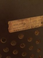
I noticed that as well. However, the attached photo shows the label that is found on the rear pressboard panel of the console. Also, searching for "1MV358R" ('8' instead of '9') turns up a "Magnavox Imperial 1MV358R console TV".
Attachments

so with all the output tubes removed measure/test for voltage at pin 2 on the sockets (check all sockets) there should be nothing there.
Last edited:
It is pretty simple to replace the faulty capacitor.
It will most likely be the yellow ones. You can cut the old one out and solder the new one in its place.
Check the voltages with the four output tubes removed and make sure all the pin 2s are at zero volts.
Replace the capacitors on any that are not zero volts.
It will most likely be the yellow ones. You can cut the old one out and solder the new one in its place.
Check the voltages with the four output tubes removed and make sure all the pin 2s are at zero volts.
Replace the capacitors on any that are not zero volts.
It is pretty simple to replace the faulty capacitor.
It will most likely be the yellow ones. You can cut the old one out and solder the new one in its place.
Check the voltages with the four output tubes removed and make sure all the pin 2s are at zero volts.
Replace the capacitors on any that are not zero volts.
When you wrote "yellow" ones, were you meaning the caps with the yellow stripes or the the ones that looks like orange (dirty yellow?) discs? Also, what does "pin 2s" mean? I'm guessing it means the second pin (clockwise in the photo) from the empty slot on the black ring where the tub sits? It seems obvious, as they have the caps attached, but I want to be sure before doing anything. I'll be asking a lot of questions.....
The "yellow ones" would be the big ones, on the lower of the two you can read 446.
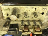
Pin 2 is the one these are attached to.
Pin 2 is the one these are attached to.
The "yellow ones" would be the big ones, on the lower of the two you can read 446.
Pin 2 is the one these are attached to.
Got it. Thanks. I will try this as soon as I get home from work tonight.
let's reference the schematic the capacitors in question are labelled C104,C105,C204,C205 (note that the values for the positive half are 0.0015 mfd and the ones for the negative half are 0.047 mfd)if you pick any output tube (V2,V3,V5,V6) find pin 2 and follow the line back towards the input you will find them.
in the photo we see three of the output tube sockets and yes going clockwise (from the gap in the pin spacing) pln1 no connection pin2 the grid (input) tracing out from here on each socket you find the cap's in question, pin 3 (cathode with no tube installed you shouldn't see voltage here) pins 4,5 heater/filament (6.3 Vac) pin 6 n.c. pin7 (plate (output) CAUTION high voltage B+ here) pin 8 n.c. and last but not least pin 9 (screen/suppressor grid H.V. caution)
my money is on the big white 0.047
Last edited:
OK here's the part where my ignorant shows. I set the multimeter to DC voltage and put the leads on each side of the large yellow capacitor. The display shows around 170-190, but if I take the leads back off, the display does not go back down to zero immediately. It takes quite a long time to whine back down to zero. Both of the large yellow caps were in this range. Am I doing this right?
no take the readings with respect to ground use a clip lead to connect your voltmeter's negative terminal to ground.
are you familiar with standard safety precautions with respect to high voltage circuits?
last thing i want is for you to hurt yourself (high voltage mistakes can kill!!) or cause damage to your amp.
i forgot you did mention this was a little outside your wheelhouse!
are you familiar with standard safety precautions with respect to high voltage circuits?
last thing i want is for you to hurt yourself (high voltage mistakes can kill!!) or cause damage to your amp.
i forgot you did mention this was a little outside your wheelhouse!
Last edited:
All of this is new to me. Like I wrote, I only have the equipment for passive wiring in guitars. I'd like to learn to make these repairs myself but I also want to live. Should I/we continue or should I take this to a pro?
Also, I assumed I was supposed to have the unit unplugged when performing these tests.
Also, I assumed I was supposed to have the unit unplugged when performing these tests.
Last edited:
With all the doubt and the fact that the work is being done by an owner whom is new to it all then perhaps all four of the capacitors aught to be replaced. The light brown ones will be 0.0015 mfd and the larger yellow 0.047 mfd ones. The 0.047 mfd yellow ones are the prime suspects but if one is out the other will be on its way out too.
Pin 2s means pin 2 on each output tube.
You can see the capacitors connected to pin 2 on each tube and you can do a web search for a data sheet for the tubes and check for yourself.
Pin 2 has to be zero volts. It is shown as negative in the data sheet but the circuit has a special resistor that keeps the cathode a little bit above zero volts to get the negative value that is shown in the data sheet. One probe of the meter goes to chassis or ground for all measurements.
when looking for voltage measurements you need the power on and with tube amps the speakers or suitable load resistor connected.(although in this case with the output tubes removed you don't need the load)
with care and reasonable precaution this can be done but if at anytime your unsure or don't feel safe stop!
a word on safety:before poking around inside any chassis you need to verify that large filter capacitors are fully discharged they can hold charge for a long time and pack a punch! make a clip lead with a 200 k ohm resistor and discharge all the large caps you have on the chassis by shorting them with your "clip lead"(with the power off of course)
is there anyone in your area that can test your tubes? if so they would be likely candidates to assist you in this
also take some time to learn about "Dim Bulb Tester" (google that)
Last edited:
I just bought two pair (Matched) of ECC21 for my Prima Luna, the amplifire has a Automatic Bios Regulator, however i have the same issue with obe of the Tubes ,-S
I just bought two pair (Matched) of ECC21 for my Prima Luna, the amplifire has a Automatic Bios Regulator, however i have the same issue with obe of the Tubes ,-S
I think you must had the tube name wrong. The automatic bias will be on the output tubes, and if you meant ECC81, then that is not an output tube, and would not have its bias set that way.
- Home
- Amplifiers
- Tubes / Valves
- One tube brighter/hotter than the others