Right. So what your seeing at the output of your amplifier might not be the amplifier. You have to isolate from what you see on the scope.
Is your amplifier in a case or just trapped to a heat sink sitting on your bench.
Try to find the source of the RF and shut it down.
I know of one DIYer who spent two days trying to find an oscillation in his amplifier only to find it was ingress. His amp is actually well behaved.
I have no case yet, just amp pcb trapped to a heat sink.
The most probable sources of RF ingress is PC and wi-fi router. I'll try to measure when they are off.
I wouldn't know if your compensation is adequate. I'm just saying wherever there is local gain/FB and you have a local oscillation this circuit is suspicious.
Than should I try to locate local gain/FB around Q17 and complementary by the method you discribed, not touching the components?
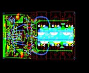
double layer pcb
Well, in the good old days we easily got away with this. Now days with modern components you need take care of the return path much more diligently than in the past. It is advisable to consider a solid ground plane between your routing layers. Also it is advisable to take great care of the signals need a dedicated ground trace to the common reference point.
To sum it up as previously stated, more sophisticated layout following basic high speed guide lines is needed.
Also, if you have to put more than 10pF capacitors everywhere to tame things down you have major problems with the circuit.
I thought the best solution is star grounding technic, not a ground plane.
There is a dedicated ground trace for input part of the amp pcb which than goes to common power GND refference by wire (not shown on layout).
I redesinged the layout a bit. Will this variant be better than previous? From decoupling caps there will be separate wires to a common power GND plane
There is a dedicated ground trace for input part of the amp pcb which than goes to common power GND refference by wire (not shown on layout).
I redesinged the layout a bit. Will this variant be better than previous? From decoupling caps there will be separate wires to a common power GND plane
Attachments
I have no case yet, just amp pcb trapped to a heat sink.
The most probable sources of RF ingress is PC and wi-fi router. I'll try to measure when they are off.
An enclosure would help a lot. Can you drop it into a grounded metal container?
It doesn't have to be a permanent enclosure.
Than should I try to locate local gain/FB around Q17 and complementary by the method you discribed, not touching the components?
No. Deal with the RF ingress problem first so your not chasing your tail.
You don't know yet if the amplifier is actually oscillating.
I thought the best solution is star grounding technic, not a ground plane.
There is a dedicated ground trace for input part of the amp pcb which than goes to common power GND refference by wire (not shown on layout).
I redesinged the layout a bit. Will this variant be better than previous? From decoupling caps there will be separate wires to a common power GND plane
You do want a ground plane, you do want to connect this ground plane to your common reference point. You do want to route ground signals you care for as dedicated traces on your routing layer to the common reference point.
I am afraid your variant layout without a plane layer between the routing layers will exhibit the same issue you are facing now.
You should familiarize with the concept of ground planes and high speed routing techniques. This will help you understand that what I am trying to tell you.
You need to develop a habit of thinking about the return path of your signals, just connecting something to 'ground' and then forget about it is not helping. This is not DC but AC and at slightly elevated AC frequency a new set of layout routing rules apply than for plain DC stuff.
If it's RF interference, it will be "talking". Set the time base to audio/video frequency range and see if there is any modulation present. Zoomed in to see the carrier frequency this is often missed.
Once that is ruled out, you need to determine whether it's local or global (loop). The fixes are different.
Once that is ruled out, you need to determine whether it's local or global (loop). The fixes are different.
RF ingress has absolutely nothing to do with your PCB design or layout.
And adding large planes would only make it worse for RF ingress problems because large planes act as antennas and do nothing for the problem.
Your problem, assuming it is RF and not local oscillation is solely because the circuit is not in an grounded enclosure. If the source is local then turning it off will help but if it is broadband then there is no hope.
It's a simple solution that doesn't require complexity.
What do you mean by grounded?Your problem, assuming it is RF and not local oscillation is solely because the circuit is not in an grounded enclosure.
Grounded at least to the ground of the circuit. Earth ground also helps but we know earth grounding can be a problem with audio.
Earth ground is for safety only. I'm also not convinced the enclosure needs to be connected to the circuit, a faraday cage for instance
What do you mean by grounded?
connected to GND refference I guess
I tried with all home appliances off in the room, but the same result. Perhaps the scope itself produces RF noise or just FM radio signal in an air.
Will try to find some steel or alu case tomorrowRF ingress has absolutely nothing to do with your PCB design or layout.
And adding large planes would only make it worse for RF ingress problems because large planes act as antennas and do nothing for the problem.
Your problem, assuming it is RF and not local oscillation is solely because the circuit is not in an grounded enclosure. If the source is local then turning it off will help but if it is broadband then there is no hope.
It's a simple solution that doesn't require complexity.
Attachments
![20171126_225852[1].jpg](/community/data/attachments/582/582971-36bf313c72a9b2a77f3e87e943a05065.jpg?hash=Nr8xPHKpsq)
Last edited:
Earth ground is for safety only. I'm also not convinced the enclosure needs to be connected to the circuit, a faraday cage for instance
With the ultra low distortion oscillator I designed and build it made a big difference grounding the enclosure to the circuit ground. It wasn't enough just to have a solid ground plan on the PCB.
These days audio frequency is my hobby. My day job is RF.
I agree with the Faraday cage. I'm really just trying to make a strong point.
A deep turkey pan would be good enough to conduct a test to see if this is ingress or an unstable circuit.
Earth ground is for safety only. I'm also not convinced the enclosure needs to be connected to the circuit, a faraday cage for instance
I have no Earth GND in my wall socket (have to rebuilt a mains wiring in my house). I can only connect to circuit GND currently.
If you attach the ground clip of you probe to the probe tip and then look at you scope with same settings the question about your scope generating what you see will be answered.
This is fine. It will do more than an earth ground.I have no Earth GND in my wall socket (have to rebuilt a mains wiring in my house). I can only connect to circuit GND currently.
We are just testing a theory. You want to see if the apparent oscillation amplitude decreases with shielding. If it does then it is likely ingress. But if there is no difference then you likely have a local oscillation in your circuit.
Who knows you may have both.
Last edited:
When tried to check the other ch. out (with different output bias method - diodes string) the scope showed little less oscillation if I'm not wrong. However this test is done with different position of slope level on a time base unit of the scope. On the first photo the triggering signal isn't going through time base unit, on second photo with setting a slope level on some single point, the signal goes through time base to the scope (it's seen by a light of small green led in the midle).
Found an alu case. Will I have to put in there the amp on heatsink and probe with only wires going out from a cover?
The last two photos are inside a case.
Found an alu case. Will I have to put in there the amp on heatsink and probe with only wires going out from a cover?
The last two photos are inside a case.
Attachments
![20171126_234922[1].jpg](/community/data/attachments/583/583053-9d2fb2629b4c25ce5f93560cbfce07b2.jpg?hash=nS-yYptMJc)
![20171126_235006[1].jpg](/community/data/attachments/583/583069-39b951625a96f17b2b9bdf0091acff16.jpg?hash=OblRYlqW8X)
![20171127_002424[1].jpg](/community/data/attachments/583/583155-2622f9fcc21642b7f3dd193f04b8e450.jpg?hash=JiL5_MIWQr)
![20171127_002506[1].jpg](/community/data/attachments/583/583169-529674b9febcbb4faab550fc5012dfc1.jpg?hash=UpZ0uf68u0)
Last edited:
- Home
- Amplifiers
- Solid State
- One of the Top Solid-State CFA amp design