Hi Scott,
Any progress? If you have a spare IRF610, you could try it. How did you verify the zeners?
Chris
Any progress? If you have a spare IRF610, you could try it. How did you verify the zeners?
Chris
Chris:
No progress so far. I suspect the problem is incredibly simple to diagnose if you understand how the circuit works; I don't have the background (love the music, love designing the projects, enjoy the assembly and have no idea how to debug -- brilliant, no?).
Trying to follow Tarasque's advice, I have rechecked the voltage across the 7 zener diodes -- each drops about 9.1 volts and the zener voltages on the bad power supply are consistent with those on the good power supply. I assume therefore that the zener's are fine.
I have also rechecked the voltage across the IRF610:
The gate is 89.9 v (65.3 v on the good ps)
The drain is 98.2 v (98.1 v on the good ps)
The source is 94.6 v (62.8 v on the good ps)
The voltages on both sides of D5, R1, R2 and R3 are similar on both power supplies.
I have at least 6 or 7 IRF610 mosfets that can be sacrificed, but don't want to waste them needlessly.
What am I missing?
Regards,
Scott
When you were checking the voltage drop across the zeners, you were using red probe on cathode and black on the anode of each zener?
I think Tarasque's advice of checking what current is going thru the zener stack is a good idea. You would do this by lifting one end of one zener and inserting your DMM in series with the lifted end and the next zener. Meter in mA mode, probably on highest range to start with if not autoranging. I'm not sure what current you might see if the stack is conducting properly? But if you see no current, that means one of them is bad for sure.
If you have spares, you could change them all out. I think I have a bunch of them, and could send you some if you wanted to try this.
An externally hosted image should be here but it was not working when we last tested it.
I think Tarasque's advice of checking what current is going thru the zener stack is a good idea. You would do this by lifting one end of one zener and inserting your DMM in series with the lifted end and the next zener. Meter in mA mode, probably on highest range to start with if not autoranging. I'm not sure what current you might see if the stack is conducting properly? But if you see no current, that means one of them is bad for sure.
If you have spares, you could change them all out. I think I have a bunch of them, and could send you some if you wanted to try this.
Scott,
Just wondering if you could post close-up shots of the top and bottom of the two psu boards? It's always possible we'll be able to spot something you've missed!?!
cheers
Paul
Just wondering if you could post close-up shots of the top and bottom of the two psu boards? It's always possible we'll be able to spot something you've missed!?!
cheers
Paul
Pars and spzzzzkt:
Thanks for offering to help. I'll post a couple of photos, but I suspect they won't help much.
I have additional zeners, which can be swapped in for the ones on the board. I'm not sure which probe was used on the anode and which on the cathode; does it make a difference? Another question: I've assumed that since each zener on the "bad" board is dropping 9.1 v, each is working fine. Is that a bad assumption?
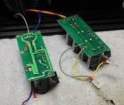
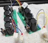
Here's one photo. One leg of the extra resistor (100r 2 watt) is soldered to a ground connection; the other end of the resistor is only connected when the caps need to be drained.
So what's the deal with these zeners?
Thanks, Scott
Thanks for offering to help. I'll post a couple of photos, but I suspect they won't help much.
I have additional zeners, which can be swapped in for the ones on the board. I'm not sure which probe was used on the anode and which on the cathode; does it make a difference? Another question: I've assumed that since each zener on the "bad" board is dropping 9.1 v, each is working fine. Is that a bad assumption?
Here's one photo. One leg of the extra resistor (100r 2 watt) is soldered to a ground connection; the other end of the resistor is only connected when the caps need to be drained.
So what's the deal with these zeners?
Thanks, Scott
Attachments
Scott,
I would think if each zener individually shows a 9.1V drop, that if you measured from end to end you should have 7 x 9.1V, or ~64V dropping across the stack. So junction of R1/R2 to ground should be 64V. Top of R1 to ground should be 60Vac * 1.414 - (2 * 0.7), or about 83.4Vdc. And across R1 should be 83.4V - 64V or about 19.4Vdc. This assumes you are using a 60Vac transformer.
Beyond that I'm not quite sure how the rest of it works. I would ohm out all the resistors and connections to ensure that everything is connected and resistors are not blown.
Scott,
I know we've been obsessing about zeners, but have you looked at the orientation of D5 (1N4001) on the faulty supply? The voltage across cap 3 looks like it might be only a little more than a diode drop from the full rail voltage which could suggest that D5 is reversed or faulty.
cheers
Paul
I know we've been obsessing about zeners, but have you looked at the orientation of D5 (1N4001) on the faulty supply? The voltage across cap 3 looks like it might be only a little more than a diode drop from the full rail voltage which could suggest that D5 is reversed or faulty.
cheers
Paul
Paul,
Well noted! could well be the reson of the problem, but does not explain the high gate voltage as I see it.
Scot,
Pls check the resistors in your PS board and the continuity of the traces.
I've seen metal film resistors fail to open state. I'm not sure if this will explain the high gate voltage, but as long as the gate voltage is incorrect, it never will produce the correct output.
A reverse diode will put high voltages across the Gate/source and can damage the fet. If the fet failed, it could also cause the gate resistor to fail, isolating the gate effectively.
Scott,
I suspect you have 9.1V zener installed in D5 rather than a 1N4001.
I was going off your original measurements in the above post. The most recent set show a 9.1V difference between Drain and the voltage across C3.
It looks like in the first instance you had the 1n4001 reversed, and have then replaced with a 9.1V zener before making the second lot of measurements. Try replacing the D5 with a 1N4001 in correct orientation. I'm pretty sure this will fix your problem.
cheers
Paul
Guys:
Thanks for the suggestions! D5 is definitely an 1N4001, but I'll check the orientation this evening when I get home from work. The resistors and associated traces will be checked as well.
Again, thanks for your patience and advice! I'll post a note as soon as I get a chance to look at the board.
Regards,
Scott
Paul:
Just the IRF610. I'll be heading home soon and expect to post some test results in a few hours.
Regards,
Scott
Just the IRF610. I'll be heading home soon and expect to post some test results in a few hours.
Regards,
Scott
Scott,
The Zen Variations Part 3 pdf ( http://www.passdiy.com/pdf/zen-ver3.pdf ) has an excellent description of how the basic regulator works. Values are different but the principles are the same. The key difference is the addition of an RC filter (R2/C3) in the P1.7 psu.
The zener string and R1 should give you 64V regardless of whether the IRF610 is installed or not.
Before you try anything else you should make sure the zener voltage reference is working correctly.
- Remove IRF610 then check the voltages between the junction of R1/D6 and ground. You need to verify you have 64V at this point.
- If you still have ~89V between R1/D6 and ground with IRF610 removed, try lifting one end of D5 or removing it completely and recheck the voltages. D5 is a protection diode for the mosfet so removing it while the IRF610 is out won't be problem.
You don't need to worry about measuring the gate/source/drain voltages at this stage.
best
Paul
Paul, Tarasque and everyone else interested in a laugh:
Here's the latest readings (with the IRF610 installed):
C1 to Gnd = 97.2 v
C2 to Gnd = 97.2 v
C3 to Gnd = 64.1 v
C4 to Gnd = 96.9 v
D6 to D12 voltage drop = 64.2 v
Junction R1 & R2 to Gnd = 64.2 v
Other end (top) of R1 to Gnd = 97.4 v
V drop across R1 = 32.8 v
D5 is properly oriented and is a 1N4001 (could this have been fried?)
R1 = 2.2k (measured after a minute or so)
R2 = 4.7k (ditto)
R3 = 219 (ditto)
R4 (none installed)
R5 = 3.4r (ditto)
I didn't remove D5 since I was reading about 64 v to Gnd.
Ideas?
Muchos albondigas,
Scott
Scott,
Thanks for posting those measurements. That pretty much eliminates the zener string, R1 and D5 from the list of suspects.
What do you measure from '610 gate to ground?
There aren't that many components left in the chain... so it looks that your problem could well be around the IRF610 itself. The solder pads are fairly close, so it might be worthwhile checking that there are no solder bridges, component leads touching, etc. Using the continuity test on your DMM is probably the quickest way to check this.
Paul
Ps you might need to replace your IRF610 - it has a rating of Vgs of +/-20V - the maximum difference in voltage between gate and source - beyond which the gate insulation is damaged. The differential you are measuring is currently in excess of 30V...
It might be worthwhile using a load on the output of the supply - that should drop the unregulated rails back towards 80V. Maybe a 2k resistor?
Folks:
I hate saying it, but I give up. The zeners and D5 were replaced, the resistors checked, the big caps are fine and I cannot figure out what the hell is wrong with this power supply. I've removed parts so often that some of the solder pads have lifted off. I'm not a stupid person, but this is, for some inexplicable reason, completely out of my league.
Is there anyone who has the time and the expertise to fix this board for me? All I ask is that you tell me where the problem(s) resided. I'll happily pay for parts and shipping (US residents strongly preferred).
Many thanks,
Scott
Hi there! Buy some boards from te local electronics shop and make a hardwired psu. There is a lot of stuff about how to make a psu on this forum, and don't give up, its worth it! Mojo Teake
Under other circumstances, I'd agree with you. In this case, the project is for a friend. Everything has been drilled and situated in both the power supply and preamp enclosures, and Veteran's Aleph P 1.7 power supply boards have been specially laid out to fit the power supply chassis. I really need to use this board (or another identical pcb), which is why I'm now resorting to asking for help.
Regards,
Scott
Regards,
Scott
- Status
- Not open for further replies.
- Home
- Group Buys
- (one more) ALEPH P 1.7 clone