spzzzzkt said:That is definitely how I would have the caps installed. cap + should be oriented to signal source.
Ok, so in 2 weeks I will back home and I will have just 1 day to play with capacitors and others stuff, than I will leave for 2 more weeks or so.
I will report my further results. 🙂
cheers
Peppe
noelectrix said:“helps" 🙂 (not to say "this IS the answer")
THE answer IS the portion I quoted 😀
Of course while I've been pointing other people to instructions on how to setup the P1.7 for maximum performance I've had mine setup completely the opposite to the instructions. 12dB attenuation on the DIP switches and maximum gain on the right/left level controls.
Now rectified.
edit: this is actually makes a fairly obvious improvement to the clarity of the preamp. It's like a free upgrade 😉
Now rectified.
edit: this is actually makes a fairly obvious improvement to the clarity of the preamp. It's like a free upgrade 😉
It's worth checking the setting of the VR's with a multimeter. When I measured resistance on the 2 VR's at the physical minimum gain, one read 2.001K the other was 1.936K - a 3.2% difference.
If you are going to the effort of matching resistors and transistors it's probably worthwhile adjusting the VR's to the same values.
Peppe, which points are you measuring the voltages at?
cheers
Paul
If you are going to the effort of matching resistors and transistors it's probably worthwhile adjusting the VR's to the same values.
Peppe, which points are you measuring the voltages at?
cheers
Paul
Hi Paul,
I won't be at home before almost ten days.
Please, tell me all that you think about my troubles.... 🙂
I will have 1 day to make all measurements and than I will leave again... 🙁
cheers
Peppe:
I won't be at home before almost ten days.
Please, tell me all that you think about my troubles.... 🙂
I will have 1 day to make all measurements and than I will leave again... 🙁
cheers
Peppe:
Little update:
- Oriented all the + of capacitors to signal source
- Set the switches to the minimum gain (1.3 dB)
- Set the trimmers to the maximum gain for both channels
Results:
- Voltage in R17/18 and R 35/36 is betweens .59 to .61 for both channels
- Voltage across input caps is still around 20 Volt
- Voltage across output caps is still betweens 54-57 Volt
I had very little time for measurements but I used the pre with a T-Amp like final (SE input-output of course) and all was fine. No hum, no noise, nothing wrong.... apparently....
I will be back at home in others 10 days for further checks.... but which one?!
cheers
Peppe
spzzzzkt said:this is actually makes a fairly obvious improvement to the clarity of the preamp. It's like a free upgrade 😉
Hi Paul,
Could you list what you'v done in total to optimize the performance?
Hi Peppe, did you fixed it??
I had similar problems (60V on the output caps) in my first version, later I discovered that I was using irf610 insted of irf9610 on T3 and T10
Now is working and sounding very nice. 🙂
Paul, could you please advice about optimizing it ?
thanks
ciao
.vale.
I had similar problems (60V on the output caps) in my first version, later I discovered that I was using irf610 insted of irf9610 on T3 and T10
Now is working and sounding very nice. 🙂
Paul, could you please advice about optimizing it ?
thanks
ciao
.vale.
Ciao Valeriano,
thanks for suggesting.
I will be back at home in 10 days and I will check all parts, active and passive as well. I need time and till now it was not the case.
ASAP I will be back on topic. 🙂
cheers
Peppe
thanks for suggesting.
I will be back at home in 10 days and I will check all parts, active and passive as well. I need time and till now it was not the case.
ASAP I will be back on topic. 🙂
cheers
Peppe
Peppe, good luck with your pre.
I'm using RIFA PHE426 as coupling caps and the sound is very good.. wanted to experiment a bit with other caps.. where should I source blackgates ? anyone ?
thanks
.vale.
I'm using RIFA PHE426 as coupling caps and the sound is very good.. wanted to experiment a bit with other caps.. where should I source blackgates ? anyone ?
thanks
.vale.
There used to be an italian distributor that had Cerafines and I thought BlackGate? Audiokits maybe? Others would be hificollective in the UK.
In the US:
http://www.soniccraft.com
http://www.percyaudio.com
http://www.partsconnexion.com
I've personally always wanted to try the PHE426s in the P1.7 that I am building. WHat are you using and where did you source them? These are hard to find in the US.
Chris
In the US:
http://www.soniccraft.com
http://www.percyaudio.com
http://www.partsconnexion.com
I've personally always wanted to try the PHE426s in the P1.7 that I am building. WHat are you using and where did you source them? These are hard to find in the US.
Chris
Hi Pars!
thanks for your message, really appreciated.
personally I'm using phe426 10uF both input and output,I've got them from member Ruach (james).
I like the sound but wanted to try blackgates.
RS and Farnell stocks rifa phe426 upto 4.7 uF, you may want to try some paralleled.
ciao
.vale.
thanks for your message, really appreciated.
personally I'm using phe426 10uF both input and output,I've got them from member Ruach (james).
I like the sound but wanted to try blackgates.
RS and Farnell stocks rifa phe426 upto 4.7 uF, you may want to try some paralleled.
ciao
.vale.
Problem solved!
It was wrong value of R17: 4.75K instead 33.1. Arg!
Usually I solder the same component on both channel and
this is the second time I make the same error on both channel.
Do you use to finish and test one channel a time?
Do I have to change my way to populate the boards? 🙄
BTW: input caps are 9-10V and output 28-29V (left ch) and 27-30V (right ch).
There is a problem because 1-2V o difference?
While the pre is playing, I am working on the rear pannel.
Do I have to wire input and/or output to the star-ground?
Of course the work is not done. I would to thanks you for helping
and ASAP I will post my listen impression... before and after
changing the capacitors on the signal path... 😉
Cheers
Peppe
Folks:
I recently finished my Aleph P 1.7 and would like to express my appreciation to Veteran, Nelson Pass, Mikkel Simonsen and everyone who contributed to this thread. The preamp sounds wonderful (especially after being burned in with a FryKleaner for two weeks) and mates beautifully with my Aleph 1.2 amps. This was a huge project for a relative newbie with very limited background in the electronic arts, and it wouldn't have been possible without your help.
Thank you all very, very much!
Regards,
Scott
Attachments
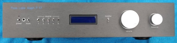

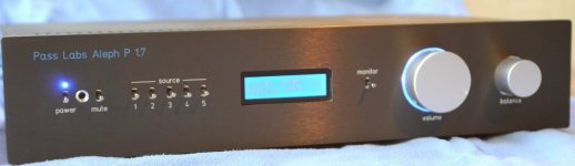
Ouch, that umbilical entry especially itches my pleasure mode button.
(what is it with that mechanism of bad boys and rough hardware ?)
Very sleek looking, yer DIY majesty, bet you a nickel Paaah will be proud of you.
(what is it with that mechanism of bad boys and rough hardware ?)
Very sleek looking, yer DIY majesty, bet you a nickel Paaah will be proud of you.
Very nice! Did you do the case yourself, or what is it made up of? Looking at the pics, I assume you did a sep. PSU?SRMcGee said:Folks:
I recently finished my Aleph P 1.7
<snip>
Again, very nice job, very clean look.
Chris
- Status
- Not open for further replies.
- Home
- Group Buys
- (one more) ALEPH P 1.7 clone