If I could only see the values of the parts used. But thanks anyway.
Then use your own values.
I was hoping to learn a bit more about the operating points and appropriate OT specification. I'm guessing ~9W rms is achievable at AB1.
I was hoping to learn a bit more about the operating points and appropriate OT specification. I'm guessing ~9W rms is achievable at AB1.
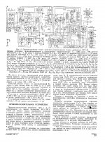
Sure. KRU-10 receiver had 10W output power.
????????? ????????? ''???-10''.
Thanks Anatoliy.
You are welcome.
Transformers there were mediocre, for 100 Hz - 5KHz band, since it was an AM radio, for a horn speaker on a pole, for a collective farm without AC, so it was a battery powered receiver.
As you may see, 4P1L were triode connected.
Yes, very nice. I have been studying odd harmonic cancellation on triode PP amps that hopefully can deliver more involving experience. Planning to develop a hybrid PP 4P1L, dual SE approach to avoid zero magnetic crossing and H3 cancellation. So, thanks again, now I have a solid target, 10W in AB1, perhaps a bit over 15W in AB2.As you may see, 4P1L were triode connected.
By a stroke of good fortune, I found the complete article of the schematic Wavebourn posted in #974. Here is the link in case anyone else is interested RadioKot :: Audiophile amplifier 4P1L (in Russian) or Google translated to English.
Little pentode push-pull
This topology is very interesting to see with DHP ...
Pentode amplifiers can sound very well. I will show an little well succeeded (good sounding) pentode project (but is not an DHP project...🙁):
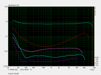
I have a small valve amplifier in my car 🙂eek:! well, DHP here is impossible😀), using 6EM5 and EF86 (IDHP) that sounds pretty good, and I have some measurements of the same here. This thing have less 3H than I expected from pentodes, but have more higher H than some triode or SIT projects.
My schema is also "Schade feedback" like this (but with pure pentode output), except that my scheme have a fundamental difference, made possible due to the IHDP use: the input stage is "differential" due to use of high valued cathode resistor (with proper grid biasing scheme).
Schematics... I are at work now, and if someone have some curiosity I publish here when at home.
Here is from Russian forum: 2P29L driving 4P1L

This topology is very interesting to see with DHP ...
Pentode amplifiers can sound very well. I will show an little well succeeded (good sounding) pentode project (but is not an DHP project...🙁):
I have a small valve amplifier in my car 🙂eek:! well, DHP here is impossible😀), using 6EM5 and EF86 (IDHP) that sounds pretty good, and I have some measurements of the same here. This thing have less 3H than I expected from pentodes, but have more higher H than some triode or SIT projects.
My schema is also "Schade feedback" like this (but with pure pentode output), except that my scheme have a fundamental difference, made possible due to the IHDP use: the input stage is "differential" due to use of high valued cathode resistor (with proper grid biasing scheme).
Schematics... I are at work now, and if someone have some curiosity I publish here when at home.
Attachments
Original thread: A2 drive...
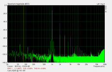
I have not been very successful to try the A2 amplifier with 4P1L using, in my case, 5687 to drive the grid 4P1L😡🙁. The sound was bad and the next measurement clearly showed that.
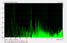
It's been almost one year of this trial, and I found the measurement today into one "lost" file. I did not insist on the topology as I tried other projects at the time and abandoned the idea (please ignore the 60Hz interference, I solved this trouble after it, but I not saved, futhermore this 60Hz shows severe IMD products in the 1kHz signal and is more instructive).
This terrible looking FFT starts only after 4P1L g1 conduction; is a by-product of A2 operation in this particular case. Makes sense: non-zero Z from cathode follower and drastic Z change at g1 at starting conduction.
Maybe in the Wavebourn example results in far more clear waveshape...
I have not been very successful to try the A2 amplifier with 4P1L using, in my case, 5687 to drive the grid 4P1L😡🙁. The sound was bad and the next measurement clearly showed that.
It's been almost one year of this trial, and I found the measurement today into one "lost" file. I did not insist on the topology as I tried other projects at the time and abandoned the idea (please ignore the 60Hz interference, I solved this trouble after it, but I not saved, futhermore this 60Hz shows severe IMD products in the 1kHz signal and is more instructive).
This terrible looking FFT starts only after 4P1L g1 conduction; is a by-product of A2 operation in this particular case. Makes sense: non-zero Z from cathode follower and drastic Z change at g1 at starting conduction.
Maybe in the Wavebourn example results in far more clear waveshape...
Attachments
In my case the sound was exceptionally clean, one triode strapped 6J9P cathode follower was driving 2 paralleled 4P1L grids. 2.4K primary transformer.
I consider the possibility of having displayed some instability/oscillation due to test layout, or bad bias/tube choice, but I did not figured out at that moment.
As usual (obviously), as seen, the ideal is to follow the original recommendations unless the person is with measuring equipment or open/honest ears to venture into the new.
As usual (obviously), as seen, the ideal is to follow the original recommendations unless the person is with measuring equipment or open/honest ears to venture into the new.
I tested this with my old trusted DC supply lab with filament bias. Measured zero ripple here.
The negative supply (for cath follower for A2) has some ripple but I filtered this and not solved the 60Hz intrusion.
BUT:
I found some short notes I made about this testing and yes, the trouble can be related to oscillations, but:
I tested the output with CCS (Gary Pimm BBCCS) and not "normal" trafo or choke loaded. I found a little trouble with oscillations with this CCS and I solved this (initially I put the 4P1L in check but is the CCS), or at least I think so because later I found some trouble related again with this CCS, in other project (MTA style amp). This time I revised the CCS and this trouble in MTA are relative to the CCS (and finally I solved 100%, and this project showed perfect measurements), but at this time the 4P1L project are fully disassembled so I don't tested again to see if this A2 effect reduces when the output is operating correctly (maybe yes, maybe not). But I imagine a drastic reduction in ripple intrusion due to correct operating CCS.
Guys like TubeLab prefers to use MOSFET to class A2 projects, and make some sense due to g1 Z change but I consider the 4P1L too little to need "force brute" driving...
In short, a little detail can make a final difference in projects... (I used too small valued resistor in MOSFETs gates so the CCS oscilates in RF)
And probably this CCS error changed the sound much more than A2 character since A2 bend only occurs with high volume. My bad.... I don't remembered this when I saw the measurement.
Last edited:
.. since A2 bend only occurs with high volume....
Mosfet follower effect is audible even at low power: controlled and definite bass.
I'm using "powerdrive" (source follower) since a few years, it's worth trying.
Last edited:
Hello
The oscillations in the tube,,,how does it sound through the speaker,,,or can it not be heard
Best Bjarne
The oscillations in the tube,,,how does it sound through the speaker,,,or can it not be heard
Best Bjarne
Mosfet follower effect is audible even at low power: controlled and definite bass.
I'm using "powerdrive" (source follower) since a few years, it's worth trying.
I use a 7N7 as DC coupled cathode follower driver with 7193A input stage on my 4P1L amp . Sounds much better than having a coupling cap to the output stage .
316A
If the amplifier oscillates within the audio band (due to decoupling errors or wiring errors), will be audible, but if oscillates in Radio Frequency, we cannot hear in principle but: this will change the correct bias or something like, and the sound sometimes become distorted or noisy when playing music, or sometimes changes only a little.Hello
The oscillations in the tube,,,how does it sound through the speaker,,,or can it not be heard
Best Bjarne
If amp oscillated very bad in RF sometimes we can hear some power supply ripple/hum in speakers.
Coupling cap is between the first stage (VAS) -I usually use heater biased 841 as first tube with cascode CCS as anode load- and source follower (CCS load to B- and DC coupled to output tube/s/ grid)... having a coupling cap to the output stage .
- Home
- Amplifiers
- Tubes / Valves
- One more 4P1L SE