1 tube of 4p1l fixed bias is -10.5v 4ma then 2 tubes fixed bias is -21v 8mA right? If screen grid resistor 1M feeding -21v the current will be too low? 0.02mA not 8mA?This is how I'd rebuild my previous 4P1L PSE with fixed bias and A2 drive:
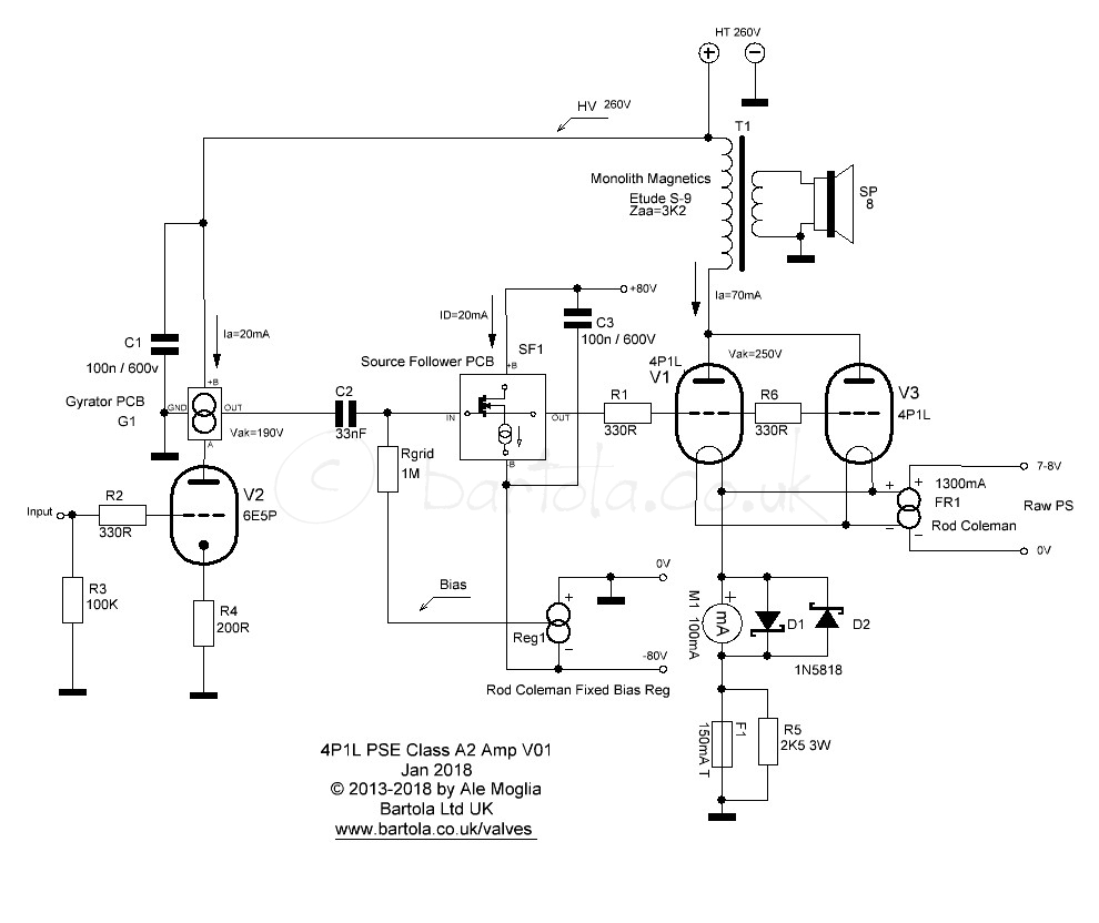
The driver is the 6e5p (or better 6e6p-dr) which is very linear and works well with a bit of degeneration in the cathode. As the stage is a hybrid mu-follower (i.e. gyrator load) the reflected cathode resistor in the anode isn't impacting the output impedance. The follower is a classic MOSFET (high GM, low Crss) follower using a symmetric +/-80V to provide enough headroom. The HT is a bit marginal for the driver but provides good headroom for the 4P1L.
The rest of the circuit is self explanatory
As I don't need the A2 power, I end up with the 4P1L PSE with filament bias I have now. Probably will rebuild this version as the follower drives well the PSE pair. I'd go for 3 valves next time.
Hope this helps.
Cheers
Ale
"1 tube of 4p1l fixed bias is -10.5v 4ma then 2 tubes fixed bias is -21v 8mA right?"1 tube of 4p1l fixed bias is -10.5v 4ma then 2 tubes fixed bias is -21v 8mA right? If screen grid resistor 1M feeding -21v the current will be too low? 0.02mA not 8mA?
No.
Each /paralleled/ tube fixed bias is -10.5V.
There are -practically- no DC current (uV region) trough 1M (FET gate) bias voltage resistor.
if feeding -10.5V through 1M bias resistor, only some uV will pass through the bias resistor and current will be very low at 0.01mA."1 tube of 4p1l fixed bias is -10.5v 4ma then 2 tubes fixed bias is -21v 8mA right?"
No.
Each /paralleled/ tube fixed bias is -10.5V.
There are -practically- no DC current (uV region) trough 1M (FET gate) bias voltage resistor.
Then, what 4mA screen grid in Tube data sheet related to? Thank you.
Sorry, I don't understand that what's the relationship between FET's gate DC current (if it even really producing) and (trioded pentode) power tube's screen current?
Sorry, due to my little knowledge. I would like to change question. What is the purpose of the datasheet information of -10.5V 4mA screen grid of 4P1L use for (if not for the purpose of fixed bias)? Thank you.Sorry, I don't understand that what's the relationship between FET's gate DC current (if it even really producing) and (trioded pentode) power tube's screen current?
I read information from www.hupse.eu/radio/tubes/4p1l.htm website shows Vg -10.2V and mAs 4 mA are this the fixed bias voltage and current?Where are you read this information?
Screenshot?
https://www.bartola.co.uk/valves/2016/03/10/russian-pse-in-steroids-01a-into-4p1l-part-iv/"1 tube of 4p1l fixed bias is -10.5v 4ma then 2 tubes fixed bias is -21v 8mA right?"
No.
Each /paralleled/ tube fixed bias is -10.5V.
There are -practically- no DC current (uV region) trough 1M (FET gate) bias voltage resistor.
from website of Mr. Bartola https://www.bartola.co.uk/valves/2016/03/10/russian-pse-in-steroids-01a-into-4p1l-part-iv/
the screen voltage is -24VDC (not uV). However there is no 1M bias resistor and 330R grid resistor.
That is the point I do not understand why if feed -10.2V to 1M bias resistor there is no DC (uV only) but another -24VDC has no 1M bias resistor and feed -24VDC instead of uV.
If are you read carefully, these numbers are valid at penthode mode, at specific Ua, Ug, Us values.
The linked (made by Ale) schematic contains triode connected pentode tubes, with other subject to conditions.
Triode connected pentode tube's -summed- anode current contains both currents (Ia, Ig2), so at development -in itself- does not need to be considered Ig2.
The linked (made by Ale) schematic contains triode connected pentode tubes, with other subject to conditions.
Triode connected pentode tube's -summed- anode current contains both currents (Ia, Ig2), so at development -in itself- does not need to be considered Ig2.
sorry, it's typo: uA.not uV)
Practically there are no DC current (or FET was damaged).
The 1M is the load of previous stage (enough large, because coupling capacitor is small).
Hence, no DC current pass through 1M but there is -10.2v pass through 1M, am I correct?sorry, it's typo: uA.
Practically there are no DC current (or FET was damaged).
The 1M is the load of previous stage (enough large, because coupling capacitor is small).
-10.2vdc , in micro ampre (uA) current?
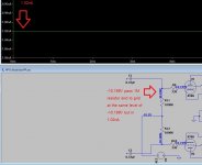
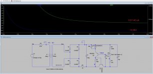
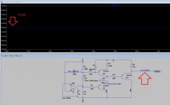
I borrow KT88 PP fixed bias in this forum and try to test -10.2V pass through 1M bias resistor."1 tube of 4p1l fixed bias is -10.5v 4ma then 2 tubes fixed bias is -21v 8mA right?"
No.
Each /paralleled/ tube fixed bias is -10.5V.
There are -practically- no DC current (uV region) trough 1M (FET gate) bias voltage resistor.
the result is voltage is little drop from -10.2V to -10.199V and current is about 1.02nA. Is it correct, Mr. Euro21? Thank you very much in advanced.
Attachments
Each /paralleled/ tube fixed bias is -10.2V."1 tube of 4p1l fixed bias is -10.5v 4ma then 2 tubes fixed bias is -21v 8mA right?"
No.
Each /paralleled/ tube fixed bias is -10.5V.
There are -practically- no DC current (uV region) trough 1M (FET gate) bias voltage resistor.
1. Why this picture is -20V? (10.2+10.2)
2. Why this picture has no 1M ohms fixed bias resistor?
https://i0.wp.com/www.bartola.co.uk...s/2012/12/4P1L-PSE-version-01.png?w=951&ssl=1
Thank you
I haven't used the 4P1L for several years but I'm revisiting it. Not filament bias this time, just ordinary cathode bias.
I'm just checking that this pinout for 2x 4P1L in triode is optimum, so comments welcome. The two 4P1L are connected internally in series, and then in parallel so total filament is 4.2V at 650mA. Anode, grid2 and grid3 connected together, no added resistors. 250V on the anode and 35mA each tube.
Is this how you would do it?
I prefer to parallel wire the 4P1L, to reduce the skewing of the bias along the length of the filament -> sounds better.
Filament current is now 1.3A total, so if you are heating them with my regulators, you can compare the parallel pair to a 300B without changes to any parts.
Filament current is now 1.3A total, so if you are heating them with my regulators, you can compare the parallel pair to a 300B without changes to any parts.

I read somewhere that series connection with the cathode resistor at the centre point, pin 8, gave slightly more gain.
Mr. Coleman...can one regulator be used for both power tubes in the Posh Pu ll amplifier? You had previously commented that two regulators should be used.I prefer to parallel wire the 4P1L, to reduce the skewing of the bias along the length of the filament -> sounds better.
Filament current is now 1.3A total, so if you are heating them with my regulators, you can compare the parallel pair to a 300B without changes to any parts.
Last edited:
????I read somewhere that series connection with the cathode resistor at the centre point, pin 8, gave slightly more gain.
If the filament structure is symmetrical (for example V, M, W) and anode has equal space from whole length of half filament wires, I don't understand why would change the gain for any mode.
- Home
- Amplifiers
- Tubes / Valves
- One more 4P1L SE