I read all the 15 pages of Bryan’s thread and some other references on net like duyparadise “The etude preamp” and I decided to build this preamp, too.
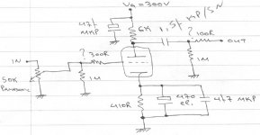
I build it like Brett suggested to GAK. It’s like the attached schem.
The only thing I changed is that I'm using 7 parallel 39K carbon 2W resistors as anode load.So anode load is around 5K6.
Values of grid stoppers and grid leak resistors are of my choice.
So if you’d like to do any comments to develop this schem I’d be very glad.
I don’t like to do major changes like feeding a CCS anode load or put chokes in the PSU or e.t.c.
I’d like to leave it as it is. I already have built the preamp in a very nice chassis so I can’t do major changes.
I’d like comments like different bias points or different values of components that will affect my preamp’s sonic quality or e.t.c. In a few words, I’d like to do changes that it’ll not cost me too much and it’ll not be needed to change the chassis dimensions.
And now some questions.
-Frank said in Bryan’s thread that if you’d like to feed the 12B4 with 6,3V filament voltage just connect pins 3&4 or 3&5 and solder the wires at pins 3&5 or 3&4. Is this correct? I have connected pins 4&5 and solder the wires at 3&4.
With this connection what exactly I have done? Sorry for this newbie question but I’m a little bit confused.
-I have connected the signal path at pin 2 of 12B4A. Is it better to use two grid stoppers at pins 2 and 7 and connect the signal path at the two ends of these resistors?
-Are the grid stoppers necessary in this project?
-I also mention that these tubes are microphonic. What can I do for this?
I have put the ceramic sockets directly to the upper of the chassis with the volume control and RCAs, too. So when I touch the knob of the volume control or the interconnect cables I hear a pop at my speakers. When I touch the tubes pop it’s much louder.
-I have a hum problem, too. It’s not very loud but audible. I’m thinking to solve this problem by connecting a cap or/and resistor from star earth to chassis. But, what are the best values for this purpose? Can I use the same values for my amp? Right now I have put a 100n cap at my amp at the same point and it’s dead quiet. Is this a safe value? I read somewhere that it’s better to use a resistor and NOT a cap. Why?
Over here I’d like to explain you how I have grounded my preamp.
I have used a multi-star earth method. I have one earth point at the negative of the input RCA at the L-channel that all grounds go from the circuit and, the same thing at the R-channel. Then, these two earth points go to another earth point that there are all the grounds of the PSU. From that point a wire goes to chassis at the same point where main’s earth and the CT of the filaments are. Hope you will understand my description. My English are not very strong.
Attachments
Hum problem
resident:
Here is a post extracted from another forum:
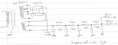
"For rectifiers with cathodes, take the DC from the cathode, rather than from the filament Ct. If the dc is taken from the filament ct with a cathode type rectifier, a 60 Hz component from the filament supply will be added to the dc output, plus some dc will pass through the filament. This may not be a significant amount, but why add in any 60 Hz, as it is more difficult to filter than is 120 Hz."
This may help,
John
resident:
Here is a post extracted from another forum:
"For rectifiers with cathodes, take the DC from the cathode, rather than from the filament Ct. If the dc is taken from the filament ct with a cathode type rectifier, a 60 Hz component from the filament supply will be added to the dc output, plus some dc will pass through the filament. This may not be a significant amount, but why add in any 60 Hz, as it is more difficult to filter than is 120 Hz."
This may help,
John
Thanks for this!
In another forum I read that it's better to take DC from CT but I didn't thing about that there's danger to add 50Hz(over here) or 60Hz on it.
If I can't hum with another way I'll try it.
In another forum I read that it's better to take DC from CT but I didn't thing about that there's danger to add 50Hz(over here) or 60Hz on it.
If I can't
hum with another way I'll try it.That'll be fineresident said:I build it like Brett suggested to GAK. It’s like the attached schem.
The only thing I changed is that I'm using 7 parallel 39K carbon 2W resistors as anode load.So anode load is around 5K6.
The op points don't make a lot of difference once the 12B4 has some current running through it. I'd reduce the cathode bypass cap a bit in value though to 100u.I’d like to leave it as it is. I already have built the preamp in a very nice chassis so I can’t do major changes.
I’d like comments like different bias points or different values of components that will affect my preamp’s sonic quality or e.t.c. In a few words, I’d like to do changes that it’ll not cost me too much and it’ll not be needed to change the chassis dimensions.
The filament is centre tapped, so by connecting it this way it allows you to use a 6V3 heater-Frank said in Bryan’s thread that if you’d like to feed the 12B4 with 6,3V filament voltage just connect pins 3&4 or 3&5 and solder the wires at pins 3&5 or 3&4. Is this correct? I have connected pins 4&5 and solder the wires at 3&4.
With this connection what exactly I have done? Sorry for this newbie question but I’m a little bit confused.
If it makes you feel better, do it. I've don't think I've bothered with stoppers on the 12B4.-I have connected the signal path at pin 2 of 12B4A. Is it better to use two grid stoppers at pins 2 and 7 and connect the signal path at the two ends of these resistors?
-Are the grid stoppers necessary in this project?
I build my chassis to start with assuming the tubes are microphonic and have come compliance between the chassis and the sockets.-I also mention that these tubes are microphonic. What can I do for this?
12B4s have two problems- quite variable distortion performance and quite variable low frequency noise. Selecting tubes is the single biggest improvement you can make.
What's the cathode voltage in your circuit? I'm wondering about alternatives to the RC circuit there (I hate big caps in audio circuits...).
What's the cathode voltage in your circuit? I'm wondering about alternatives to the RC circuit there (I hate big caps in audio circuits...).
Thank you guys for your help. I was woried that no one will answer me all these questions. 🙂
@Brett
Do you bypass this cap with MKP? Or are you only using a good quality electrolytic?
What do you say about the 1M resistors? Are those values ok?
@SY
Cathode voltage is around 12V. What do you say? Brett already suggested me to change the cap to 100uF.
I’d like to make you the same question I ask Brett. Do you bypass this cap with an MKP one? Or are you only using a good quality electrolytic? Say Elna, Black Gate,etc?
@Brett
I’ll try it. Thanks for this tip.I'd reduce the cathode bypass cap a bit in value though to 100u.
Do you bypass this cap with MKP? Or are you only using a good quality electrolytic?
My way or Frank’s way? Frank has confused me. I thing connecting pins 4&5 and solder the filament wires at 3&4or5 is the right way.The filament is centre tapped, so by connecting it this way it allows you to use a 6V3 heater
So, no stoppers. I don’t like stoppers,too. Remove 100 ohm too?If it makes you feel better, do it. I've don't think I've bothered with stoppers on the 12B4.
What do you say about the 1M resistors? Are those values ok?
Can you explain me how exactly you did it? I have a big problem with this. I can’t even touch the volume.I build my chassis to start with assuming the tubes are microphonic and have come compliance between the chassis and the sockets.
@SY
I don’t know why but I’m starting to hate them, too.What's the cathode voltage in your circuit? I'm wondering about alternatives to the RC circuit there (I hate big caps in audio circuits...).
Cathode voltage is around 12V. What do you say? Brett already suggested me to change the cap to 100uF.
I’d like to make you the same question I ask Brett. Do you bypass this cap with an MKP one? Or are you only using a good quality electrolytic? Say Elna, Black Gate,etc?
Real quick reply re the cathode cap. If you remove it the gain will go down from about 5.5 to 4 and output Z from about 900R to 2k5 or so. If 4 is enough, remove it.
Also SY has been experimenting with using cheap red leds to bias tubes. Maybe try that. 7 in series, two parallel strings / tube for 14/channel. I've not used it but for about $2, why not try it?
Also SY has been experimenting with using cheap red leds to bias tubes. Maybe try that. 7 in series, two parallel strings / tube for 14/channel. I've not used it but for about $2, why not try it?
12V is probably a bit high for the LED scheme at the relatively low currents of a preamp tube- the problem is that you can't get enough current through them to get the series string impedance low and onto the flat part of the Z vs I curve for the LEDs. But maybe an LM329 in series with two LEDs...
Nah. In this case, I think you're stuck with a bypassed cathode resistor. I'd use a good (not exotic) electrolytic with an FKP bypass.
Nah. In this case, I think you're stuck with a bypassed cathode resistor. I'd use a good (not exotic) electrolytic with an FKP bypass.
I don't need enough gain.So I can remove it.
I put it cause I was afraid of a bass-shy preamp. And Zout at 2k5 isn't a problem?
I'll try it, though.
Any comments about my other questions? 😕
I put it cause I was afraid of a bass-shy preamp. And Zout at 2k5 isn't a problem?
I'll try it, though.
FKP or MKP?Nah. In this case, I think you're stuck with a bypassed cathode resistor. I'd use a good (not exotic) electrolytic with an FKP bypass.
Any comments about my other questions? 😕
SY said:12V is probably a bit high for the LED scheme at the relatively low currents of a preamp tube
I think this runs at 30mA or so. So not exactly low current - unless you're used to 7242s for preamps or something 😀
Of course, an active load high Z load will reduce the current swing. making the changing slope resistance of the LED less of a concern.
There's about 30mA through the tube, so it should be enough, no? Definitely too much for an LM329SY said:12V is probably a bit high for the LED scheme at the relatively low currents of a preamp tube- the problem is that you can't get enough current through them to get the series string impedance low and onto the flat part of the Z vs I curve for the LEDs. But maybe an LM329 in series with two LEDs...
2k5 is low for many common cathode tube preamp. Should be fine.resident said:I don't need enough gain.So I can remove it.
I put it cause I was afraid of a bass-shy preamp. And Zout at 2k5 isn't a problem?
I'll try it, though.
FKP or MKP?
FKP.
resident said:My way or Frank’s way? Frank has confused me. I thing connecting pins 4&5 and solder the filament wires at 3&4or5 is the right way.
You connect pins 4 and 5 together, and apply 6.3V between pin 3 and the connected pins. Alternatively, connect 12.6V across pins 4 and 5, and ignore pin 3.
True, but with an active load, the source Z is going to go up. It still might be low enough for the specific application.
30 mils is indeed a lot of current, but the LED string will have a source Z of something like 35-40 ohms. If you use two legs in parallel, that drops, but not by a factor of two. For the push-pull circuits where I've been using them, a little impedance and a little modulation aren't too disqualifying, and they work well with CCS loads. But in this case, with a resistive load, much as I love that cheery red glow...
30 mils is indeed a lot of current, but the LED string will have a source Z of something like 35-40 ohms. If you use two legs in parallel, that drops, but not by a factor of two. For the push-pull circuits where I've been using them, a little impedance and a little modulation aren't too disqualifying, and they work well with CCS loads. But in this case, with a resistive load, much as I love that cheery red glow...
FKP caps are better in quality than MKP? Or are you using FKP caps because they’re smaller?FKP.
I agree with you. Frank has confused me a little cause he said that for 6.3V you must connect pins 3&5 or 3&4 and apply 6.3V btw pin 4 and the connected or pin 5 and the connected. See here.You connect pins 4 and 5 together, and apply 6.3V between pin 3 and the connected pins. Alternatively, connect 12.6V across pins 4 and 5, and ignore pin 3.
Any link to read more about LEDs in Push Pull amps?For the push-pull circuits where I've been using them, a little impedance and a little modulation aren't too disqualifying, and they work well with CCS loads. But in this case, with a resistive load, much as I love that cheery red glow...
Thanks again for your help. 🙂
Today I’ll do some changes to my preamp.
1) I’ll remove the bypass cap.
2) I’ll take DC from the cathode and not from the CT of the transformer.Hope I’ll have better results.
3) I’m also thinking to use a cap or/and resistor to connect ground at chassis. But which values are safe for this purpose?
And 4) I don’t know what to do with the tubes that are microphonics. Any good idea? 😕
I think the FKPs are bigger. I prefer using foil to metallized just from a worry-wart esthetic, but MKP would probably work just as well.
Those tubes are too microphonic! I touch the volume knob or the chassis and the pop is so annoying that I can't live with!So I decided to rebuild my preamp in a new chassis! 
I'm planning to use a sub-chassis for the tubes and a main chassis for everything else.
I have some questions over here.
Is it a good idea to use copper for the sub-chassis?
Any hint on placing the sub chassis to minimize vibration?
If a tube (12B4) is around 8cm (3") far from the PT, is there any possibility of hum?
And a question (in and) out of topic.
What kind of cables are you using to connect signal from the RCA to circuit?
12B4s do have to be rigorously selected for low noise (especially LF "burble") and microphonics. You'll need to buy ten to find two good ones, on average. That's one reason I wouldn't use them in a preamp.
Hmmmm....That's one reason I wouldn't use them in a preamp.

Since I'm rebuilding my preamp,I can use another tube!
And keep the four 12B4A I own, for another project.
(any good idea where to use them?)
Any good tube for a preamp?
Any link?
Please help cause I don't have a preamp
!I have a passive one
 but passive preamps are not my taste.
If religious purity is not your highest priority, but low distortion and quiet, reliable operation is, I'd use a 6SN7 in a cascaded voltage amp/cathode follower.
- Status
- Not open for further replies.
- Home
- Amplifiers
- Tubes / Valves
- one more 12B4A preamp