Yes, I attached it previously (see schematic from A77).
Instead of germanium diodes I used for simulations the 1N1183 (simulating a low voltage drop).
Rest is identical.
Instead of germanium diodes I used for simulations the 1N1183 (simulating a low voltage drop).
Rest is identical.
I am only at the "1-st order approximation" level in BJTs, FETs or CMOSs (discrete active) electronics.
Don't know what will happen exactly in the 2nd, 3rd or 4th orders of approximation. I can say it is okay-ish, or simulate and test it. But I don't know exactly what it will happen, much less if the isolation will be increased or not.
What I kind of know is that super high input impedance will invite everything connecting to it to become an antenna. I have already Hum problems...
It seems complicated for me, I cannot really answer easily your question.
You can tell me.
There should be no risk of it becoming an 'antenna' as R501 100k is setting the input impedance.
There should now be no effect on the load/buffer circuit as 100k is easy to drive, you could even set this higher if you want as JFets are voltage controlled devices.
Are you simulating in LTSpice?
There should now be no effect on the load/buffer circuit as 100k is easy to drive, you could even set this higher if you want as JFets are voltage controlled devices.
Are you simulating in LTSpice?
The 317 buffer has a near-zero output impedance, and practically no reverse transfer, meaning you do not need anything else.
The only unanswered question is the suitability regarding the noise level.
To determine whether it is acceptable or not, a listening test is the best strategy: breadboard a quick and dirty version of the buffer and connect it how it should be. For the VUmeter, it will pose no problem, but for the audio, especially headphones, the noise could be problematic
LV, the question was about reverse transfer of VU-amp. The 317 being a buffer should perform good, as you say. Well, the VU-amp should also have reverse transfer at least on the range of Hfe , if I understand correctly.
If this one has a poor reverse performance, then either two buffers or change the choice of VU-amp.
It just confuses me that in A77 sensitive placement this VU-amp brings no malign contribution, yet in my adaptation it does.
If this one has a poor reverse performance, then either two buffers or change the choice of VU-amp.
It just confuses me that in A77 sensitive placement this VU-amp brings no malign contribution, yet in my adaptation it does.
I think I sorted it out.
I changed the coupling Buffer-VUAmp capacitor(s) from Elko to Foil.
Somehow the Elko got upset between bias voltages.
Now the reverse transfer is okay and also the various AC&DC weirdnesses.
Happy, now I can plan to use a single buffer and see soon what the final design is..
I changed the coupling Buffer-VUAmp capacitor(s) from Elko to Foil.
Somehow the Elko got upset between bias voltages.
Now the reverse transfer is okay and also the various AC&DC weirdnesses.
Happy, now I can plan to use a single buffer and see soon what the final design is..
For VUmeter is clear so.To determine whether it is acceptable or not, a listening test is the best strategy: breadboard a quick and dirty version of the buffer and connect it how it should be. For the VUmeter, it will pose no problem, but for the audio, especially headphones, the noise could be problematic
I am optimistic for listening test: worst case the -113dB rms noise floor (not A-scaled) it should be enough.
If ever the PA amps will need to output 120dB SPL, it means that the noise floor at 7dB SPL should not be a problem as the venue background noise will be much louder.
Same for Heapdhones, if ever it can produce a 120dB SPL, then I guess the ears will need some time to accomodate with pause silence between notes or even between songs, to be able to hear 7dB SPL.
Do I estimate wrong?
What the 317 experience tells?
My fears that 317 will not replace well the 1-BJT CC stage, are slowly dissipated.
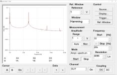
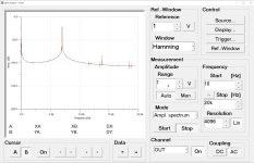
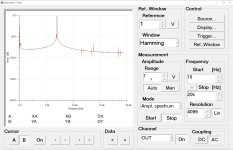
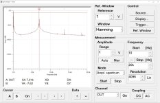
I have simulated with TinaTi its proprietary transient model for 317, and results were close to the LT-Spice proprietary model of 117, but more realistic at -102dB for 1Vp input at 1KHz.
In measurements I could measure -96dB H2 for same conditions. The H3, simulated at ca. -136dB it cannot be measured, as displayed noise floor was -111dB for this level. Still, ok-ish. If VU-amp and headphone derivations are connected, the H2 level increases marginally, only to -95dB, and noise floor average(!) drops from -113dB to -111dB (measured with BW20KHz divided in 4096Pts, and with LP@200KHz)
If input level is decreased to -10dB or -20dB then the harmonics get smaller than the noise. I checked the values also for other frequencies, like 2K, 4K, 6K, 10K and 14K, and it passed with same performance. So, the listening test should require that voicing signals will stay below -5 or even -10dB level (0dB is 0dBu). Barely a limitation.
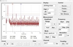
The SNR and THD being promisingly low, I tried to simulated the IMDs. This is the last concern about 317 performance.
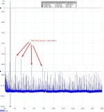
Unfortunately the standard 10:1 ratio of 7K+60Hz IMD method show a beating of 1KHz which I cannot interpret.
I will try to measure it.
If this measurement is passed, the listening test cannot be skipped.
I have simulated with TinaTi its proprietary transient model for 317, and results were close to the LT-Spice proprietary model of 117, but more realistic at -102dB for 1Vp input at 1KHz.
In measurements I could measure -96dB H2 for same conditions. The H3, simulated at ca. -136dB it cannot be measured, as displayed noise floor was -111dB for this level. Still, ok-ish. If VU-amp and headphone derivations are connected, the H2 level increases marginally, only to -95dB, and noise floor average(!) drops from -113dB to -111dB (measured with BW20KHz divided in 4096Pts, and with LP@200KHz)
If input level is decreased to -10dB or -20dB then the harmonics get smaller than the noise. I checked the values also for other frequencies, like 2K, 4K, 6K, 10K and 14K, and it passed with same performance. So, the listening test should require that voicing signals will stay below -5 or even -10dB level (0dB is 0dBu). Barely a limitation.
The SNR and THD being promisingly low, I tried to simulated the IMDs. This is the last concern about 317 performance.
Unfortunately the standard 10:1 ratio of 7K+60Hz IMD method show a beating of 1KHz which I cannot interpret.
I will try to measure it.
If this measurement is passed, the listening test cannot be skipped.
Attachments
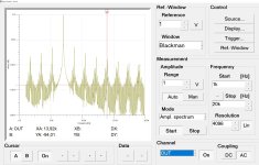
The sideskirts around the 7 kHz peak give me the impression that the settling time is insufficient.
I cannot do measurements so fast, but I will post more 'simulation IMDs'.
Any idea if this will sound acceptable as usual, or terrible?
Any idea if this will sound acceptable as usual, or terrible?
Attachments
As I said, the only way forward is experimentation, but I am relatively optimistic: the headphones tests I made with my other varieties of regulator chip-amps didn't reveal obvious flaws
This remark is for me alone: the last difficult part remaining here is to organize a A/B/C listening test, between old 3xBJT board, the 1-BJT and the 317.
It is manageable. But, beyond this I am not fully sure what means 'experimentation'.
I mean, if the component values within the topology will change the IMD, then I could only test what is proposed. Else, if the IMDs depend strictly on the active components and not on surrounding components, then it is straightforward.
This said, I wonder if there is a 'IMD optimized' topology&values surrounding the 317, or the 1-BJT.
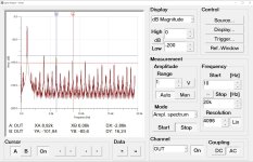
The simulation results with 317 today are on the edge, with -50 to -60dB products. If these products would come by THD alone, I know that I can easily hear this level for pure tones. Except that the IMD products are more similar to H3, hence more towards high pitch and metallic.
It is manageable. But, beyond this I am not fully sure what means 'experimentation'.
I mean, if the component values within the topology will change the IMD, then I could only test what is proposed. Else, if the IMDs depend strictly on the active components and not on surrounding components, then it is straightforward.
This said, I wonder if there is a 'IMD optimized' topology&values surrounding the 317, or the 1-BJT.
The simulation results with 317 today are on the edge, with -50 to -60dB products. If these products would come by THD alone, I know that I can easily hear this level for pure tones. Except that the IMD products are more similar to H3, hence more towards high pitch and metallic.
Last edited:
funny thing which must be mentioned, I simulated IMDs for all versions which I have today (1 BJT-CC, 1BJT-EC, 317 plus the original 3xBJT line amp):
My conclusion is, that I should not bother with A/B/C tests. Just the 317 one and verify that I did not do any trivial building mistake.
Of course, I am open to see&study any other examples where the IMDs are significantly smaller, for example better or much better than -80dB. If possible, -96dB or more. For reference we can use 1:1 (0dBu output) 1100/1000Hz tones. We can use the 60/7000Hz method as well, no problem.
- the winner by -68dB is the 317
- the second place is shared by the original circuit with 3xBJT, the 1x BC547 in CC topology (emitter follower) and the 1x BC327 in CE topology (the VU-amp from Revox): with -65dB.
My conclusion is, that I should not bother with A/B/C tests. Just the 317 one and verify that I did not do any trivial building mistake.
Of course, I am open to see&study any other examples where the IMDs are significantly smaller, for example better or much better than -80dB. If possible, -96dB or more. For reference we can use 1:1 (0dBu output) 1100/1000Hz tones. We can use the 60/7000Hz method as well, no problem.
Last edited:
Being at the successful end of my task, now I can 'disclose' the off-topic details:
On the table it was my idea to redesign-reconcept the A77's Repro-PCB (1.077.720), and by means of smart non-invasive changes to replace the previous 3-BJT lineamp+phones (Q803, Q804 and Q805) with the following requirements and challenges:
Since the Balance Pot is disconnected the Pins 11-12 are freed.
- then new Outputs are : 10 - Line Out, 11 - VU-meter (rerouted) and 12- Headphones (rerouted via Volume Pots P301/302).
Now A77 is similar to B77, and even a bit better.
The new VU-amp is working fine and the listening test for Line and Headphones will be shortly organized.
One of OP's here can now change the Thread name, if this is appreciated as a good idea. Many DIY-audio friends here have asked me how "niche solution" my project is. It is niche indeed, but the numbers of A77 still 'living' is beyond 100K units worldwide. I know that in my town the vintage shops are full of them - probably suffering from these limitations. I found the original Revox solution as too much confusing and improper.
Cheers & best regards/Ionmw
On the table it was my idea to redesign-reconcept the A77's Repro-PCB (1.077.720), and by means of smart non-invasive changes to replace the previous 3-BJT lineamp+phones (Q803, Q804 and Q805) with the following requirements and challenges:
- I made a separated OpAmp simple low-noise preamp mini-circuit to bring the 20mVrms to 0dBu (and disconnected from Volume Pot!). I placed this circuit physically over the GND-shield of the Balance Pots (P303/304). The wires were rerouted accordingly.
- then 1-BJT buffer (Q803) as line output + derivation via Volume Pot to Headphones.
- then derivation to VU-amp (Q805).
Since the Balance Pot is disconnected the Pins 11-12 are freed.
- then new Outputs are : 10 - Line Out, 11 - VU-meter (rerouted) and 12- Headphones (rerouted via Volume Pots P301/302).
Now A77 is similar to B77, and even a bit better.
- Line Out is separated from Headphones and from volume Pot
- VU-meter acts for Play as well, and values are independent from Volume Pot
- VU-meter is not anymore measuring the EQ-curve (NAB/IEC have high frequency bumps) or the Line-In: it always display the proper flat 'Line-Out' in every mode of operation.
- all changes are 100% reversible. No PCB was permanently modified.
- last but not least, the original Revox A77/B77 sound quality was fully preserved. Either with 317 or with 1-BJTs, the circuits will perform equally or slightly better as the original.
The new VU-amp is working fine and the listening test for Line and Headphones will be shortly organized.
One of OP's here can now change the Thread name, if this is appreciated as a good idea. Many DIY-audio friends here have asked me how "niche solution" my project is. It is niche indeed, but the numbers of A77 still 'living' is beyond 100K units worldwide. I know that in my town the vintage shops are full of them - probably suffering from these limitations. I found the original Revox solution as too much confusing and improper.
Cheers & best regards/Ionmw
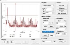
correction of simulation results: the measurements show IMDs are better than -90dB, probably -93dB (close to the theoretical CD quality).the winner by -68dB is the 317
My setup is limiting, as second source is not as good as the first one and I record too many harmonics below 100dB. I don't know for sure which one is what.
I think that for this application the 317 is excellent.
Sorry I have'n bother to test the others. Probably they are equally good.
- Home
- Source & Line
- Analog Line Level
- One BJT line amp/buffer