Hi,
today I finally finished (almost) one of my Aleph-X monos. After some minor wiring problems (half the amp was dead) I got it up and running.
So far it seems to be allright. Relative offset is around 10mV, absolute offset could be set to zero.
Bias was around 4A with 27k for R11 and R33 (VR1 and VR3 set to zero)
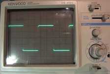
One thing that isn´t like it should is the frequency responce and the square wave.
Frequency responce is not falling like it should but rises maybe 1-1.5dB at 100kHz then is flat again at 200kHz before it falls like expected.
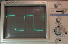
Square wave at 10kHz as quite some overshoot but looks very wel dampened with only two halve waves until it´s flat.
So I suppose I should place a cap parallel to the feedback resistor or is there another place more suited?
Until now I didn´t connect R12 and R34 to keep things simple.
William (very happy🙂 🙂 🙂 🙂 🙂 🙂 🙂 🙂 🙂 )
today I finally finished (almost) one of my Aleph-X monos. After some minor wiring problems (half the amp was dead) I got it up and running.
So far it seems to be allright. Relative offset is around 10mV, absolute offset could be set to zero.
Bias was around 4A with 27k for R11 and R33 (VR1 and VR3 set to zero)
One thing that isn´t like it should is the frequency responce and the square wave.
Frequency responce is not falling like it should but rises maybe 1-1.5dB at 100kHz then is flat again at 200kHz before it falls like expected.
Square wave at 10kHz as quite some overshoot but looks very wel dampened with only two halve waves until it´s flat.
So I suppose I should place a cap parallel to the feedback resistor or is there another place more suited?
Until now I didn´t connect R12 and R34 to keep things simple.
William (very happy🙂 🙂 🙂 🙂 🙂 🙂 🙂 🙂 🙂 )
If you've got a rise in the frequency response, then try a few pF across the feedback caps. A small value like 2 to 5pF should do the trick. Certainly no more than 10pF. Look for a -3dB point around 100-150kHz (although I'm not shy about going higher).
Grey
Grey
Hi Grey,
I tried 10pF as I can´t find any 5pF caps. This makes the square wave perfect at 1Khz, very slightly rounded at 10kHz and not so perfect anymore at 100kHz. I didn´t measure frequency responce yet.
I will activate the active current sources next and go for 50% to start with.
The amp is behaving very well although my voltage is a bit higher than expected (22V instead of 20) so heatsink temp is also a bit higher at 8A of bias. I now get 53°C at 22°C ambient for around 350 watts dissipation.
Rel offset starts at 12mV and goes down to 6mV after warm up. Absolute offset is now 0V when warm but I´ll have to look at the startup value at the next start from cold.
The diodes are not as hot as expected but the chokes can´t be touched 60°? I will measure them as soon as everything is working.
The transformer is very, very quiet (I can´t hear it at all!). Never had one of these before.......
William
ok,
some more information.
I´ve connected the 10pF caps (C2, C4). This looks good now although maybe a bit too rounded at 10kHz (I´ll try to post some pics tomorrow).
Then I put some pots at the R12 and R34 position (started with 680 Ohms), turned on the amp and gor a nice signal on the scope although I didn´t put one into the amp😱 Oscillation!
So I tried some 1nF caps for C9 and C10. This got rid of the oscillation but the square wave had a bit overshoot again and was somewhat "sloped". I changed the caps to 4n7 after trying 1n5 and 2n2. This took care of the overshoot but not of the sloping........
Next I measured the power into 8, 4 and 2 ohms:
100watts, 178 watts, 256 watts
This was a bit too much! Especially the 2 Ohm sinus had some nice distortion at the 0V position long before clipping.
Looking at the AXE-1 sheet this should be more than 75% ac-current-gain.
So I set the pots to 1k. The result was the same so I went to 2k5 wich was a bit too much (56 watts/4 Ohms).
After trying a few more settings I came to 1k3 wich gave 100 watts/ 8ohms, 160 watts/ 4 ohms and 80 watts/2Ohms. This is around 55% ac-current-gain and I will leave it there for the moment.
After this I looked again at the 10kHz square wave. The "sloping" was gone and it actually looked very nice🙂 I think it was caused by the way too high ac-current-gain setting.
Frequency response is 140kHz -3dB, 217kHz -6dB. At 20 kHz it is down by 0,2dB.
to be continued.........
William
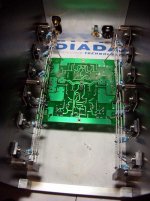
and here is the amp section. You can see the two heatsinks and the back. Heatsinks are Fischer SK57 (300x200x85mm, ca. 0.2°K/W). The fets on the minus side are matched to <0,01V (All have 4,58V Vgs at 1.1A current) The positive fets are matched in two pairs of three. I tried to get the same value when adding Vgs for the left and right side and took the same value for the sence fet (where the bias is set) So plus left was 4,56 (sence) 4,57 and 4,61,
right plus was 4,56 (sence), 4,59 and 4,60.
Source resistors are 3x1Ohm/1% per fet.
right plus was 4,56 (sence), 4,59 and 4,60.
Source resistors are 3x1Ohm/1% per fet.
Attachments
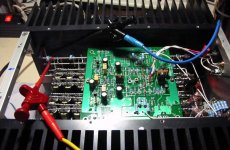
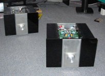
and here a view from above. Here you can see the output resistors (12x1Ohm 1%) connected directly to the output terminals. Feedback is also taken from here (so I could use the same cheap silverplated copper wire for the output connection😉 )
The resistors from output to ground (4x390Ohm) are on the board.
The resistors from output to ground (4x390Ohm) are on the board.
Attachments
input caps are 10uF BG N (no bypass yet), resistors are mostly 1% CONRAD metalfilm with some 0,1% resistors for feedback and diff pair. The input fets are matched to 0,001V (3,739 and 3,740).
Upon startup rel. DC offset is now 18mV, absolute offset is smaller 0,3V and somehow stays there.
I´ve reduced bias to 7A to make it possible to touch the heatsinks for a few more seconds. 58° somehow makes me feel uneasy but maybe I´ll convince myself that everything is allright some day.......
I´ve listened to it (mono , Dynaudio audience 42) The music is sounding nice but I can´t say a lot more at this moment.
The last picture shows both amps. The second one still needs the fets mounted, board populated etc. This will take me at least 6 weeks as I´m of to South Africa for the next three weeks and after that in Sweden for two.
I would like to thank Nelson, Grey, Chad and all the other who made this project possible!
William
Attachments
Hi Uli,
no. These are called C7 and C8 in Chad´s schematic. What would be the advantage using these?
William
no. These are called C7 and C8 in Chad´s schematic. What would be the advantage using these?
William
They reduce open loop gain. This is often necessary to
avoid phase problems as at a high frequency often the
amp turns phase in such a way that NFB might become
positive FB resulting in oszillation.
Uli

PS: I do not know Chads schematic, therefore I referenced
to a public known circuit. I am absolutely sure that NP put
those caps in his AX series too!
avoid phase problems as at a high frequency often the
amp turns phase in such a way that NFB might become
positive FB resulting in oszillation.
Uli
PS: I do not know Chads schematic, therefore I referenced
to a public known circuit. I am absolutely sure that NP put
those caps in his AX series too!
Hi Uli,
I´ve tested it up to 1MHz. I can´t see any oscillations and frequency response is down 3dB at 140kHz 6dB at 217kHz. If there´s no problem to fix I think I can leave them out can´t I?
William
I´ve tested it up to 1MHz. I can´t see any oscillations and frequency response is down 3dB at 140kHz 6dB at 217kHz. If there´s no problem to fix I think I can leave them out can´t I?
William
Hi William,
I see from the posts before that you put some caps into the
circuit. Without precisely knowing this particular circuit I am
not able to tell anything about it.
In my amps I put 15p parallel to the feedbackresistors (100k),
1n parallel to the bjt´s ce (in ccs) and another 1n as Cdom.
Very close to the Aleph 2 circuit.
In fact it is possible to stop oszillation at many different points.
I just used the standard textbook Cdom for default VAS stages.
All different possibilities to stabilize the amp do basically the
same:
They reduce open loop gain in such a way that you have some
phase margin left for applying NFB.
Uli
Hi,
just look at the Aleph-X WIKI for Hifizen/Gratakus schematic.
I uses 2x 10pF parallel to the feedback resistor and 4n7 in the active current source (3n3 would probably also do the job)
William
just look at the Aleph-X WIKI for Hifizen/Gratakus schematic.
I uses 2x 10pF parallel to the feedback resistor and 4n7 in the active current source (3n3 would probably also do the job)
William
I would put the Cdom in. The resistor parallel Rnfb increases
NFB with higher frequency to form a lo pass. With Cdom the
amount of NFB stays constant. This improves stability.
Uli
NFB with higher frequency to form a lo pass. With Cdom the
amount of NFB stays constant. This improves stability.
Uli
And what would be Cdom? 🙂 Rnfb would be the negative feedback resistor?uli said:I would put the Cdom in. The resistor parallel Rnfb increases
/Hugo
Cdom is called like this in various pieces of literature.(Self et al.)
It is the cap in the VAS between base (gate) and collector(drain).
Yes Rnfb Is the feedbackresistor from output to -in.
Uli
PS: from what I learned dom is an acronym for dominating pole
It is the cap in the VAS between base (gate) and collector(drain).
Yes Rnfb Is the feedbackresistor from output to -in.
Uli
PS: from what I learned dom is an acronym for dominating pole
wuffwaff said:
Upon startup rel. DC offset is now 18mV, absolute offset is smaller 0,3V and somehow stays there.
William
Well after putting the lid on the amp absolute offset went to +4V........
Had quite a bit of work coming back under 1V since the holes in the lid are in the wrong place. I can´t adjust VR2 without taking it off making the procedure a bit difficult. Will think of this for the next project!
I now checked absolue offset from (stone) cold:
startup -8V
5 min -4.3V
20 min -2.25V
60 min -0,3V
it sort of creeps up very very slowly after that. I suppose that´s because my little room gets warmer and warmer.....
The transformer has also developed a little bit of mechanical hum (would have been too good to be truth). So I suppose I´ll have to decouple it from the frame with some rubber.
I also have a bit of hum in the speaker (can hear it when my ear´s nearer 10cm to the woofer). I hope I can get rid of this by shielding the chokes with some mu-metal sheet. Or maybe it is gone when connected to my X-BOSOZ.
William
- Status
- Not open for further replies.
- Home
- Amplifiers
- Pass Labs
- One Aleph-X working, One to go