bocka said:
OH! That was just me sticking a bunch of diodes into a schematic that Frank had posted previously here.
Yes, you're right, the ZEN V5 is a push pull amp. But with one additional cap to the gate of the BUZ905...

🙂
se
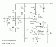
I have tried a number of one-transistor amplifying circuits with BJT's and power MOSFET's. The only amp that could be considered as a very good sounding (in terms of high-end) is the one that I am attaching. The current source in Source branch is a must to obtain low distortion. Inductance or resistors or bulbs used instead of the current source are interesting challenge but do not lead to good sounding circuit.
Attachments
back to this thread.
so whats better? 🙂
In a source follower:
A) Use a choke load and a 4700-10,000uf coupling cap?
B) Use a 1:1 OPT load with no coupling cap?
This is with a circuit that is 24vdc supply and 4A bias on a MOSFET.
Just wondering if I should try the OPT or just choke load it with a coupling cap....?
Thanks!
I think a choke and a good quality coupling cap might be the easiest way to get a good sounding amp. Transformers are tricky to get right I think. OTOH a 1:1 transformer operating at low voltages can be bifilar wound, which should be an advantage.
If you´re giong to wind your own stuff a choke will definitely be easier.
If you´re giong to wind your own stuff a choke will definitely be easier.
txs!
so for 25vdc and 4A which mosfet should I try?
should there be anything I should be aware of to protect the mosfet from the chokes reactance?
Finally, which coupling caps are good for output caps?
so for 25vdc and 4A which mosfet should I try?
should there be anything I should be aware of to protect the mosfet from the chokes reactance?
Finally, which coupling caps are good for output caps?
25Vdc x 4A = 100W, you´ll need a big one! I´d suggest you use two or three mosfets in // with adequate source resistors for current sharing. There are plenty of Mosfets suitable for this, say IRFP 140, IRFP 150 or something like that. Plenty of Mosfet disussions in the Pass labs forum.
A "flyback" diode from source to drain might be necessary, but those are often integrated in modern mosfets.
BTW it seems that protecting diodes has been up in this thread before...
I´d use 3x 2200uF low ESL/impedance caps. Caps made for switching PSU´s are usually low loss types, look for such.
Remember to bypass with quite a few uF of nice plastic film caps, or even better, paper in oil caps.
dshortt9,
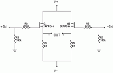
you will get considerably lower distortion in case you change the 8R source resistors by constant current sources. I do not know your supply voltage, so I would recommend CCS about 2A.
you will get considerably lower distortion in case you change the 8R source resistors by constant current sources. I do not know your supply voltage, so I would recommend CCS about 2A.
On the other hand, in case of balanced input signal the resistor version would be acceptable. In case of single ended input signal the CCS version is much better.
Thanks, being balanced helps. I hope to run 20V rails at 5A with 4R resistors. Found some 250W Dale NI 4R's on e-bay. BIG heatsinks. BIG 1.5 farad caps meant for stiffening in an auto.
Be careful, you are going to dissipate 94W on every of the MOSFETs ....
You might like to start with 8R resistors.
You might like to start with 8R resistors.
fan cooling?
If i use a small fan for cooling... can I get away with 1 mosfet per channel??
Thanks!!
If i use a small fan for cooling... can I get away with 1 mosfet per channel??
Thanks!!
You will have to know thermal resistance of the transistor (depends on package and chip), insulating pad and heatsink. Take into account that 1°C/W of the summarized thermal resistance will cause 100°C increase of chip temperature (provided there is a 100W power dissipation).
janneman said:
The 2SK60 and it's complementary device 2SJ18 are both enhancement types which were used by Sony in for instance their TA-N7 in the late 70's.
They were used as cascodes for the output stage, which had low-voltage bipolars driving the load.
Jan Didden
Why not the other way round ? Bipolar as cascode for the V-fet ?
First, because the bipolar has a higher Gm, which makes some things easyer, and second, because the VFET, unlike the bipolar, does not have a secondary breakdown problem - so you want to keep the voltage across the bipolar relatively low.
OK,
but wasn't the Vfet originally used (in the earlier amps ) for high speed, good linearity and because it is a voltage controlled device ?
But in the TA-N7 ( which I own ) the gain device is bibolar, is this still a Vfet amp ?
Any sense to built a single ended classA amp with N-Vfet and bipolar or mosfet current source ?
Hello, 🙂
today the 2SK70 and 2SJ20 V-Fet In this form, what alternatives might be?
hard to find.
best regards. Can.
😉
today the 2SK70 and 2SJ20 V-Fet In this form, what alternatives might be?
hard to find.
best regards. Can.
😉
Member
Joined 2006
Can someone share a circuit design using single ended 2SK60 or 2SJ18? 😀
Would be nice to mate it with a DHT preamp
(something like the circuit shown in the #23 thread)
Would be nice to mate it with a DHT preamp

(something like the circuit shown in the #23 thread)
- Status
- Not open for further replies.
- Home
- Amplifiers
- Solid State
- One (1!!) transistor clapping...

