john curl said:Protection diodes are not as necessary in this design, because there is no stepup transformer.
So what if there's no step-up transformer? What difference does that make? And how does this circuit guard against damage from ESD events?
Of course the BUZ900DP has the protection diodes built-in if I'm not mistaken. But what if someone goes and uses other devices?
However, there is no gain, either.
No gain? What do you mean? The input's driving the bottom MOSFET's gate and the output's taken from it's drain. That makes it a common source amplifier no?
se
That makes it a common source amplifier no?
Do I hear an echo in here... here... here... here...?
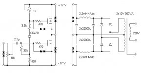
This may seem redundant, but I feel really foolish. I 'saw' a completely different circuit that what is presented here. I actually 'saw' a zener biased complementary mosfet follower, without source resistors, by an added connection and reversing the parts in my mental picture. It is a good lesson for me to look carefully first, before commenting. I like the pi filter power supply.
The more that I look at this design, the more that I see that I first missed, such as the CR470 'current source' I though that I saw a zener. This is sort of a Norton equivalent of the circuit that I normally would use. I hope that I have beaten SE to any other criticism of my initial remarks.
The more that I look at this design, the more that I see that I first missed, such as the CR470 'current source' I though that I saw a zener. This is sort of a Norton equivalent of the circuit that I normally would use. I hope that I have beaten SE to any other criticism of my initial remarks.
SY said:Welcome to the club. I've only made that mistake about a hundred times.
Oh yeah? Well I've made that mistake about TWO hundred times! So there! Nyah!
se
250 ohm Zin
Frank, I think John answered that already- presbyopia, a failing from which I suffer, too.
Frank, I think John answered that already- presbyopia, a failing from which I suffer, too.
Hi,
Thanks. That's what I'd figured too.
Cheers,😉
The input impedance of the amp..after the pot is 33K +430 Ohm...
Thanks. That's what I'd figured too.
Cheers,😉
I was wrong, and I did it from 'poor' memory. I am running out of paper, so I didn't print out the schematic. Then, in my mind, I saw 3.3 rather than 3.3k, the CR470 became a 4.7V zener, and an extra connection was made from the CR470 to the 2.2uf cap. It is a real lesson for me, but please disregard my first posts on this topic. I screwed up.
Anyway, that circuit'd work too seeing as Fuling's not insisting on a single active device. Though I don't see why you couldn't do fundamentally the same thing using a choke load instead of the active current sink.
se
se
Just a procedural point, John- you can go back and edit or delete your posts for (I think) about a half-hour after they're up. That way, you can take care of oopsies and typos yourself. If it's been longer and you REALLY want to change or delete something, just ask me or one of the other Moderators; we have magic powers.
Hi,
So the CR470 is a current source of about 8mA? Isn't the top transistor driven, if only slightly?

I see no current stabilisation resistors, wouldn't the Voffset be large?
I don't think I understand what the designer wanted....
Regards,
Thijs
So the CR470 is a current source of about 8mA? Isn't the top transistor driven, if only slightly?
I see no current stabilisation resistors, wouldn't the Voffset be large?
I don't think I understand what the designer wanted....
Regards,
Thijs
I see no current stabilisation resistors, wouldn't the Voffset be large
The off set will be large and without stability...and the amp will behave as a current source...without any damping in the load...
More an exercise than a really amplifier...i guess
Hi,
Sy,
4.70 mA according to the datasheets.
Cheers,😉
IIRC, the CR470 runs at 470 uA.
Sy,
4.70 mA according to the datasheets.
Cheers,😉
Hi,
Jorge,
So, yes it was designed for an easy load. Doesn't mean it can't be improved.
Cheers,😉
Jorge,
More an exercise than a really amplifier...i guess
Ideally suited for a FR speaker with low Qts or an actively filtered system.
So, yes it was designed for an easy load. Doesn't mean it can't be improved.
Cheers,😉
Lets put a 0.5R in the source of the lower transistor to ground and a 100uF cap from the top of that resistor to the gate of the upper transistor....
What do you think?
Regards,
Thijs
What do you think?
Regards,
Thijs
Hi Frank
The greatest problem ...is the offset....IMHO
as a FR usualy have high sensivity...and that may cause a large displacement even with a low offset voltage...
Regards
The greatest problem ...is the offset....IMHO
as a FR usualy have high sensivity...and that may cause a large displacement even with a low offset voltage...
Regards
tschrama said:Lets put a 0.5R in the source of the lower transistor to ground and a 100uF cap from the top of that resistor to the gate of the upper transistor....
Tsk tsk tsk.
Safety first, boys. 🙂
Attachments
- Status
- Not open for further replies.
- Home
- Amplifiers
- Solid State
- One (1!!) transistor clapping...