OK, i don´t like a transformer in a solid state design. It makes voltage gain, but it doesn´t make it better than the other ways to make voltage gain. And its expensive. (Lets say the truth: I have none on hand) What about going away from
- only one active device
and live with a Fet voltage gainstage in front of the amp instead of a transformer?
- only one active device
and live with a Fet voltage gainstage in front of the amp instead of a transformer?
Actually, the bias can be made stable enough at the high currents involved, and you can always employ current sensing
elements to control the bias.
aaaahhhhhh!!
This is the direction i was thinking of before
http://www.diyaudio.com/forums/showthread.php?postid=212528#post212528
only, i´m not skilled enough to make the current sensing / bias setting circuit. Does it need a small resistor in the current path and a normal transistor doing something to the gate??
Dear Nelson,
I haven't build the ZEN with an inductor that's the problems I expect. Am I right that the inductor you've used had enough resistance to make the ZEN stable?
Dear Till,
If you use a transistor as amplification stage you've got a twin transistor design...😉
I haven't build the ZEN with an inductor that's the problems I expect. Am I right that the inductor you've used had enough resistance to make the ZEN stable?
Dear Till,
If you use a transistor as amplification stage you've got a twin transistor design...😉
janneman said:That's an elegant circuit you put up.
That input transformer, is it an existing product, if so brand, type pls?
The one I had in mind is the Jensen JT-13K7-A. It's a 1:5 step-up transformer originally intended as a microphone input.
Be aware that your input impedance will be rather on the low side. If you load it with the recommended loading, the input impedance is 1.5k, so you're not going to be able to drive it with most tube circuits and passive units.
se
bocka,
i know, but i would prefer one more transistor /or differential pair over a transformer.
what about that current sensing
DC bias circuit ?
If you use a transistor as amplification stage you've got a twin transistor design...
i know, but i would prefer one more transistor /or differential pair over a transformer.
what about that current sensing
DC bias circuit ?
The resistance of the inductor will provide a DC path. If not, include a resistor into to inductor lines. I think 2 - 4 Ohms should be enough prevents the source follower from thermal runaway. This will degrade the efficency in some way. The single transistor amp as first stage seems not to be bad. It's some kind of inverted, inductor driven ZEN topology🙂
And you can include the source follower into the feedback. Or not as you like. Or someting between this, only a small amount of feedback. You should make listening experiments
And you can include the source follower into the feedback. Or not as you like. Or someting between this, only a small amount of feedback. You should make listening experiments
bocka said:The input capacitance is N^2 * Cgd, where in our given example N = 9.
A IRF530 has a Crss = Cgd = 60pF @ VDS = 25V, more if your lowering VDS.
This results in an transformed input capacitance Cin of about 5nF. Driven by a source resistance of 1kOhms the cut-off frequency is
fc = 1 / (2 * pi * Cin * Rs) = 30kHz
Given that a number of well-regarded SET amps barely make it to 20kHz, I don't see that as necessarily being problematic. 🙂
But a few points about your analysis.
First, the transformer I had in mind isn't a 1:9 step up but a 1:5. So that reduces your multiplication factor by a factor of 3.24, i.e. 25 rather than 81. Someone else plucked the 1:9 step up out of the air previously and used that as an example.
Second, your analysis assumes a purely capacitive load, i.e. your calculated impedance is based solely on the reactance of the gate capacitance. The real transformer also includes series resistance from winding resistance and series inductance from leakage inductance, so the input impedance isn't going to simply be the reactance of the MOSFET's input capacitance.
Third, since this is a source follower which inherently has 100% negative feedback, if I'm not mistaken, the input capacitance will effectively be reduced by the device's transconductance.
se
Hi Fred, thank you for your input. I have not used (as a rule) gate stopper resistors with jfets, but I have had lots of parasitic oscillation, on occasion, with jfet followers.
The most troubling case was with my Vendetta Research phono power supply. Dick Marsh had been asking me to use his new, improved caps. I was already using tin foil (RT) polystyrene caps from Rel, so I did not see the point. Well, a customer of mine, (and a good friend) had Michael Percy (sp?)modify one of my preamps with Dick's caps. He only had 200V units available and my layout was for 100V. This meant that the caps 'hung over' the board. Guess what? The jfet followers oscillated! They oscillated at about 100MHz. M. Percy did not have a fast scope, but I could see it easily. The fix was to put a 100pf mica cap in parallel with the Marsh caps. It worked well, but perhaps if I had gate stopper resistors installed, I may not have seen this happen. Keep up your input, Fred. I am glad to learn a thing or two.
The most troubling case was with my Vendetta Research phono power supply. Dick Marsh had been asking me to use his new, improved caps. I was already using tin foil (RT) polystyrene caps from Rel, so I did not see the point. Well, a customer of mine, (and a good friend) had Michael Percy (sp?)modify one of my preamps with Dick's caps. He only had 200V units available and my layout was for 100V. This meant that the caps 'hung over' the board. Guess what? The jfet followers oscillated! They oscillated at about 100MHz. M. Percy did not have a fast scope, but I could see it easily. The fix was to put a 100pf mica cap in parallel with the Marsh caps. It worked well, but perhaps if I had gate stopper resistors installed, I may not have seen this happen. Keep up your input, Fred. I am glad to learn a thing or two.
I don't wish to be a bore, but I just read some previous comments on this thread. First, we have to separate the peak voltage possible from a step-up transformer at the input of a mosfet, with the possible resonant Q of the transformer; and a normal input, even static. Static breakdown is very sensitive to the capacitance it must charge. A normal input will seldom exceed 15V or so. A transfomer could potentially 'ring' and punch through a gate. Just thinking worst case.
Yes of course Cgs is effectivly reduced by the transconductance of the source follower unfortunately not Ciss (Cgd) this is the capacitance between Gate and Drain. Cds does not have any effect to the effective input capacitance.
A 1:5 transformer reduces the input capacitance by a given Cgd compared to a 1:9 tranny. Seems to be better but has a lower gain.
The primary and secondary transformer input resistance you can transform as well as the input resistance to the output side and this lowers the cut-off frequency slightly.
50 to 100kHz is enough as frequency response. 20 kHz seems too low to me because there are some other components in the signals path (preamp, output filter from the CD, interaction between output resistance of the CD output stage and the input capacitance of the preamp...) wich will result im some other high frequency cut off. Too high bandwiths result in RF problems.
till said:i know, but i would prefer one more transistor /or differential pair over a transformer.
Why's that? Sure, transfomers have their problems at the lowest frequencies, but in my opinion they more than make up for it at higher frequencies, particularly in the midband where things seem to count more.
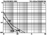
Here's a THD versus frequency plot for the JT-13K7-A that I had in mind.
It reaches its 20Hz "limit" (1% THD) at +7dBu which is about 1.7 volts RMS. The distortion curve retains the same basic characteristic, dropping like a rock and is just at 0.001% at 1kHz.
A 2 volt RMS signal such as that coming from a Red Book CD player would still have your 20Hz distortion below 2%. Hell, SET tube amps are typically rated for power at 1kHz and 3% THD.
To each their own of course. But if it's linearity you're after, I'd sure like to know of a single transistor voltage amplifier (and that means no other transistors such as current sources or cascodes) that can give you 14dB of voltage gain and be as linear as the 13K7-A.
Attachments
Why's that?
because
- i´m not experienced with them in something else than building power supplys
- as i´m no tube amp builder (i have some ECC83 etc laying around but don´t know how to use them') i have no transformer for signal laying around, never bought one, don´t know how to obtain without a lot of resarch....
- i have nothing against your design, but there must be a Zen way, as Nelson told us. I had success building Zens, i prefer to sucess building the next amp...
Hi,
Hmmm, how many good ones are there?
And how restrictive in their use are they?
Let me tell you straight, their use is very limited just as this spud presented here with an input impedance of 1K5.
Sure, it can be done...but it also starts to look like a case of intellectual masturbation to me.
So, in practice what remains is a limited BW design.... not much left of these impressive specs the Jensen offer, a FET that's on the brink of stability and a xformer that's not offering us much other than a difficult to drive Zin, putting the drive capability back to the preamp or DAC, adding some serious phase distortion in the process.
The FET is voltage driven but is exspected to convert it back into current once a speaker load is attached...no big deal except you'll have a hard time driving that load except if you can tack on yet another xformer perhaps?
As I said before it looks simple enough but isn't...
Than again, no one never said it would work anyway.
Cheers,😉
Hell, SET tube amps are typically rated for power at 1kHz and 3% THD.
Hmmm, how many good ones are there?
And how restrictive in their use are they?
Let me tell you straight, their use is very limited just as this spud presented here with an input impedance of 1K5.
Sure, it can be done...but it also starts to look like a case of intellectual masturbation to me.
So, in practice what remains is a limited BW design.... not much left of these impressive specs the Jensen offer, a FET that's on the brink of stability and a xformer that's not offering us much other than a difficult to drive Zin, putting the drive capability back to the preamp or DAC, adding some serious phase distortion in the process.
The FET is voltage driven but is exspected to convert it back into current once a speaker load is attached...no big deal except you'll have a hard time driving that load except if you can tack on yet another xformer perhaps?
As I said before it looks simple enough but isn't...
Than again, no one never said it would work anyway.
Cheers,😉
Hi,
Driving a 1K5 input with tubes is easier to overcome than what's presented after the xformer IME.
Passive attenuators are a silly idea unless they're buffered or kept on a very short leash...errr interconnect and facing an input impedance that's at least ten times higher than their own Zo, again IME.
Cheers,😉
And that pretty much just boils down to avoiding driving it with tubes or passive attenuators.
Driving a 1K5 input with tubes is easier to overcome than what's presented after the xformer IME.
Passive attenuators are a silly idea unless they're buffered or kept on a very short leash...errr interconnect and facing an input impedance that's at least ten times higher than their own Zo, again IME.
Cheers,😉
fdegrove said:Hmmm, how many good ones are there?
Quite a few apparently. Though of course your definition of "good" isn't going to be everyone else's definition of "good."
And how restrictive in their use are they?
They're certainly not for everyone.
Let me tell you straight, their use is very limited just as this spud presented here with an input impedance of 1K5.
So?
And the 1.5k input impedance is only if you load it as per Jensen's recommendations. It will be higher than that driving a higher impedance load. But so what if it is 1.5k? Don't drive it with a high impedance source like a tube output stage or a passive pre.
Sure, it can be done...but it also starts to look like a case of intellectual masturbation to me.
The same can be said of the whole Zen thing with its single-minded obsession with absolute simplicity. Who cares? This is about having some fun, remember? Why don't you go back and read the first post in this thread? Fuling wanted a power amp that used just one active device. Why? Because it'd be cool.
This pretty much says it all here:
I already own quite a few good power amps so it´s not that I need another one, I´m just doing this for the challenge.
This never started out as any sort of high intellectual pursuit. It was just something for the fun of it. Call it masturbation if you like. That's fine with me. Masturbation feels quite good. Why else do you think everyone does it?
So either get yourself a bottle of Jergins lotion and join in or go attend your MENSA meeting.
So, in practice what remains is a limited BW design.... not much left of these impressive specs the Jensen offer, a FET that's on the brink of stability and a xformer that's not offering us much other than a difficult to drive Zin, putting the drive capability back to the preamp or DAC, adding some serious phase distortion in the process.
So let's see your single transistor offering.
The FET is voltage driven but is exspected to convert it back into current once a speaker load is attached...no big deal except you'll have a hard time driving that load except if you can tack on yet another xformer perhaps?
Why would you have a hard time driving the speaker load? A follower with its lower output impedance will have an easier time of it than a single transistor common source amplifier. It will also be more linear.
As I said before it looks simple enough but isn't...
Only so much you can do with just one active device if you want a power amplifier.
Of course. But the challenge here (and the whole purpose of this thread) was a power amplifier using just one active device. If you want to talk about amplifiers using two or more active devices, start a "multiple transistors clapping" thread.
se
till said:- i´m not experienced with them in something else than building power supplys
- as i´m no tube amp builder (i have some ECC83 etc laying around but don´t know how to use them') i have no transformer for signal laying around, never bought one, don´t know how to obtain without a lot of resarch....
Fair 'nuff.
- i have nothing against your design, but there must be a Zen way, as Nelson told us. I had success building Zens, i prefer to sucess building the next amp...
Actually I wouldn't care if you did have something against it. At least as long as what you had against it was just due to your own personal preferences.
As for a Zen way, sure. Pluck off the transformer and move the inductor and the cap up to the drain. 🙂
se
Hmmm. long's you're doing that, you may as well put an OPT as the drain load and run it as a common-source amp. 'Course, you'll need a damping resistor...
bocka said:A 1:5 transformer reduces the input capacitance by a given Cgd compared to a 1:9 tranny. Seems to be better but has a lower gain.
Yup. But then I wasn't looking for a lot of gain in the first place. And Fuling's request was for just 5 or 6 watts. 2 volts RMS from a Red Book CD player along with 14dB of voltage gain and you've got about 12 watts into 8 ohms.
The primary and secondary transformer input resistance you can transform as well as the input resistance to the output side and this lowers the cut-off frequency slightly.
50 to 100kHz is enough as frequency response. 20 kHz seems too low to me because there are some other components in the signals path (preamp, output filter from the CD, interaction between output resistance of the CD output stage and the input capacitance of the preamp...) wich will result im some other high frequency cut off. Too high bandwiths result in RF problems.
Yup.
There's really just two effective ways you can use a single active device to make a power amplifier. A common source amplifier or a common drain amplifier with passive voltage gain. They both have their various limitations. The latter's limitations are basically bandwidth and input impedance. But if you design your driving circuit right, I don't see that the limitations make the design undoable and in the end it should ultimately be more linear than the common source approach.
se
fdegrove said:Driving a 1K5 input with tubes is easier to overcome than what's presented after the xformer IME.
What's presented after the transformer to overcome? You've just got the input of the MOSFET and the speaker. Or are you talking about something else?
se
- Status
- Not open for further replies.
- Home
- Amplifiers
- Solid State
- One (1!!) transistor clapping...