Fuling,
I tried the bigger source resistors to minimize thermal drift. With the original 0.33 Ohm resistor I got about 13% drift and with the new 0.68 Ohm resistor it was about 5%. This is acceptable for me because in the final version of this amp I intend to use bigger heats sinks and that will limit thermal drift even a bit more.
As to a difference in sound. I listend to it and could not hear a significant difference.
I have read somewhere that the cement and wirewound resistors I am using as source resistors are bad for the sound. Do you know if this is true and if so is there a better sounding alternative that you know of?
Tom
Tom,
Good to hear about the improvement.
I find your design very interesting, and it is one of the topologys that I consider a serious alternative for an one transistor amp.
Have to say that the current feedback troubles me a bit though, I don´t have a clue about how it will cooperate with my speakers.
I guess there is only one way to find out...!
About the wirewound resistor, I don´t know. I have never listened to resistors, so to speak. Can´t imagine that the sonic difference between different source resistors would be huge.
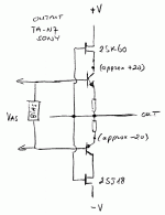
john curl said:The 2SK60 and 2SK70 are Vfets and are depletion mode devices to the best of my knowledge. I have a few 2SK60's within reach, and I might just put them on a curve tracer to be absolutely sure.
The 2SK60 and it's complementary device 2SJ18 are both enhancement types which were used by Sony in for instance their TA-N7 in the late 70's. They were used as cascodes for the output stage, which had low-voltage bipolars driving the load. The gates were directly tied to the output, giving the bipolars about +/-20V supply IIRC.
Jan Didden
Re: Re: Re: Fools Rush In Where Angels Fear to Tread
I understand why. But I'll keep that to myself. 🙂
But yes, back to one transistor clapping.
After all the valuable input I've received on the initial concept, I'd like introduce the modified version.
Peter Daniel said:This was also my impression after reading the thread. I truly can't understand, why all this argument really took place. Can we concentrate on 1 transistor clapping again? The weekend is almost over😉
I understand why. But I'll keep that to myself. 🙂
But yes, back to one transistor clapping.
After all the valuable input I've received on the initial concept, I'd like introduce the modified version.
Attachments
janneman said:The 2SK60 and it's complementary device 2SJ18 are both enhancement types which were used by Sony in for instance their TA-N7 in the late 70's.
You sure about that? John says he measured one on his curve tracer and said they were definitely depletion mode types.
se
For some reason everyone is confused about these Vfet devices. They are depletion mode, by my definition at least. You have to turn them off to control them. The proof is in the fact that they are modeled with a diode in the gate, just like jfets. Forward bias will reduce the gate impedance to a very low level. I did use devices such as this in the mid 70's when they first came out. They are very difficult to use in conventional circuits, and apparently difficult to produce cost effectively, so the Japanese manufacturers just pulled the plug on them. For a simple, transformerless one device power amp, they would be almost perfect, because they have a very low output impedance without using loop feedback, and the varying output impedance could be balanced against the transconductance to obtain a relatively linear transfer function.
Steve Eddy said:
You sure about that? John says he measured one on his curve tracer and said they were definitely depletion mode types.
se
You're right, I messed up. They are both depletion types. Sorry.
Jan Didden
Humility check....
This thread started: "I have a dream".
It is a thread of speculation and ideas. As far as I can determine, there is no finished product expected.
This is an enthusiasts forum. It is not an expert's conference.
Those without experience, or less experience, should not be told to shut up, but should be encouraged to ask questions and speculate various ideas.
A civilized discussion with the more-expert members can give invaluable insight.
Perhaps instead of "diyAudio Member" we should have our qualifications emblazened on the side-bar...? I think NOT!
This thread started: "I have a dream".
It is a thread of speculation and ideas. As far as I can determine, there is no finished product expected.
This is an enthusiasts forum. It is not an expert's conference.
Those without experience, or less experience, should not be told to shut up, but should be encouraged to ask questions and speculate various ideas.
A civilized discussion with the more-expert members can give invaluable insight.
Perhaps instead of "diyAudio Member" we should have our qualifications emblazened on the side-bar...?
I think NOT!Fred, made a number of accurate comments on this topic. I agree with him that a design with a mosfet like this should have a discrete stopper resistor directly connected to the gate, and that the gate should be clamped with a zener diode to protect it. However, without a step-up transformer, it may be difficult to charge the gate capacitance significantly enough to destroy the gate. Therefore, Nelson Pass is correct that in general, as it is not always necessary to put in a protection zener.
I once had a similar problem with a j-fet follower, interestingly enough. In this case a fellow designer returned an electronic crossover that I had designed and built for repair. I found the problem and then added protection zeners to the gates of the input part. It came back a second time, and I had to put my foot down that there was something wrong with the high fi that it was being used in. Eventually they found the problem. In a case like this, a mosfet would have blown immediately.
I once had a similar problem with a j-fet follower, interestingly enough. In this case a fellow designer returned an electronic crossover that I had designed and built for repair. I found the problem and then added protection zeners to the gates of the input part. It came back a second time, and I had to put my foot down that there was something wrong with the high fi that it was being used in. Eventually they found the problem. In a case like this, a mosfet would have blown immediately.
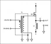
- class A
- efficiency 35-40%
- one active device
- inductice loaded
after all this very productive diskussion, is there any circuit for an inductive loaded ZEN?
- efficiency 35-40%
- one active device
- inductice loaded
after all this very productive diskussion, is there any circuit for an inductive loaded ZEN?
till said:- class A
- efficiency 35-40%
- one active device
- inductice loaded
after all this very productive diskussion, is there any circuit for an inductive loaded ZEN?
Here, I did this one just for Fuling. 🙂
Attachments
Dear Till,
I think the ZEN is a simple, very good developed amp hard to beat. It uses only one MOSFET in the signal path and has a only very few side effects. The problem when using an inductive load instead of the current source or drain resistor is that you have no DC feedback path to the gate. This basic circuit tends to be unstable because of thermal runaway.
A source follower is stable in itself with a source resistance as feedback path. An inductor has only a very low resistance. Small changes in Vgs or temperature results in large changes of drain/source current and this current changes does not result in a voltage change witch can feeded back to the gate. I can't see any easy way to make this amp stable. Maybe increasing the resistance of the inductor can make this amp stable. 2 - 4 Ohms can be a good starting point.
john curl said:However, without a step-up transformer, it may be difficult to charge the gate capacitance significantly enough to destroy the gate. Therefore, Nelson Pass is correct that in general, as it is not always necessary to put in a protection zener.
Why would it be any easier to charge the gate capacitance with a step-up transformer? The gate's going straight to ground through just 470 ohms of secondary winding resistance, compared to the Son of Zen where if you've nothing plugged in or your source is AC coupled, the only path to ground for the gate is through the load resistor, which will often be on the order of 100k ohms and in some cases as high as 1Meg.
So if it's not always necessary to use the protection zeners in the Son of Zen because it's difficult to charge the gate capacitance, seems it would be even more difficult in the case of a step-up transformer.
se
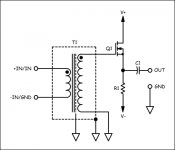
Fuling said:I sort of like your idea, but how much does that 1:9 0,9Hz-120kHz transformer cost...?
It's $101.85 in 1-3 quantities.
I know. OUCH!. 🙂
But its voltage gain is far more linear (if you're shooting for as little distortion as possible) than you'll be able to get with just a single active device. If you want to use just a single active device, it'll be more linear as a follower than a voltage amplifier.
se
Steve,
That's an elegant circuit you put up.
That input transformer, is it an existing product, if so brand, type pls?
Jan Didden
That's an elegant circuit you put up.
That input transformer, is it an existing product, if so brand, type pls?
Jan Didden
Again the high input capacitance you get with the step-up transformer. A (ideal) transformer ist often called power transformer and thats what he does. A transformer transforms the power from the input to the output. If you transform it 9-times the input voltage this means the current is 9-times less.
The other way round at a given output signal the input voltage is transformed to Uin = 1/N * Uout and the current Iin = N * Iout, because input and output power must be the same. Calculating the input resistance (or reactance) this results in
Zin = Uin / Iin = (1/N * Uout) / (N * Iout) = 1 / N^2 * Uout / Iout = 1 / N^2 * Zout.
With Zout = 1 / (2 * pi * f * Cgd)
Zin = (1 / N^2) / (2 * pi * f * Cgd) = 1 / (2 * pi * f * N^2 * Cgd)
The input capacitance is N^2 * Cgd, where in our given example N = 9.
A IRF530 has a Crss = Cgd = 60pF @ VDS = 25V, more if your lowering VDS.
This results in an transformed input capacitance Cin of about 5nF. Driven by a source resistance of 1kOhms the cut-off frequency is
fc = 1 / (2 * pi * Cin * Rs) = 30kHz
This might be enough but much worse than the ZEN and depending on the input signal. Feel free to build this amp but there are many problems to be solved. You need measurement capabilities (at least a scope and a signal generator). There is a high risk of thermal runaway. Probably you will blow some MOSFETS when testing and installing. Maybe you must optimise the inductor. That's the problems any designer has. I think there is a litte chance that this amp work. But I expect that the performance will be bad. In that case I won't build that amp. And I don't like transformers in the signal path. I do not expect that this amp will sound good although it looks simple. This amp seems to be too simple.
Of course. I have previously described just such a circuit, usingtill said:[Bafter all this very productive diskussion, is there any circuit for an inductive loaded ZEN? [/B]
a 1H air core coil (actually a full roll of magnet wire), and it worked
very well. It will probably show up as one of the Zen Variations
before the series is completed next year.
bocka said:I think the ZEN is a simple, very good developed amp hard to beat. It uses only one MOSFET in the signal path and has a only very few side effects. The problem when using an inductive load instead of the current source or drain resistor is that you have no DC feedback path to the gate. This basic circuit tends to be unstable because of thermal runaway.
Actually, the bias can be made stable enough at the high
currents involved, and you can always employ current sensing
elements to control the bias.
- Status
- Not open for further replies.
- Home
- Amplifiers
- Solid State
- One (1!!) transistor clapping...