Using top-firing coax with conical refletor seems simply enough.
But less synergly 🙂 .
AFAIK Tannoy Orbitus was the first.
Small firm in Moscow had made omny speakers with 15" RCF coax recently.
But less synergly 🙂 .
AFAIK Tannoy Orbitus was the first.
Small firm in Moscow had made omny speakers with 15" RCF coax recently.
Last edited:
 .
.In an omnidirectional synergy horn, you can put the midrange and the compression driver face-to-face, like an oreo cookie.
That works better than what's pictured in post #1, as it allow you to get tighter spacing.
Patrick, thanks for your input. I've been trying to visualize your oreo cookie. Is this sketch anything like what you have in mind? I think I'd still like to use multiple small drivers, to get the crossover freq up above the voice band.
Attachments
Post 24 and 25 will both work.
Post 24 will have issues with the vertical polars, because the walls aren't flat.
For a waveguide, you want flat walls.
Post 24 will have issues with the vertical polars, because the walls aren't flat.
For a waveguide, you want flat walls.
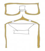
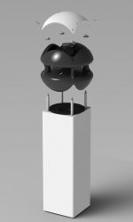
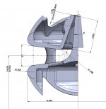
My recent acquisition of a 3D printer has inspired me to take another look at this idea.
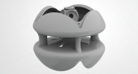
I made a drawing to show how I'm thinking about the form of the horn. This is based almost entirely on intuition.
I also made a CAD model of a possible implementation using a tweeter and woofer from an old Klipsch KG 4.5, and 4 Dayton Audio PC68 2-1/2" mids.
Any thoughts?
I made a drawing to show how I'm thinking about the form of the horn. This is based almost entirely on intuition.
I also made a CAD model of a possible implementation using a tweeter and woofer from an old Klipsch KG 4.5, and 4 Dayton Audio PC68 2-1/2" mids.
Any thoughts?
Attachments
I understand that your goal is to build omnidirectional speakers, but I wonder whether you realize that what inspired you to go this direction is actually not omnidirectional. In post # 8 you showed your proto-type "omnidirectional speakers" that used Linaeum tweeters. Linaeum tweeters, however, are inherently dipolar. See, e.g., RadioShack Optimus Pro LX5 loudspeaker | Stereophile.com
So, is it possible that the kind of sound you are looking for is actually that of dipolar speakers?
Not sure if others have already pointed this out before, but my quick scan of the thread did not identify anything conspicuous on this point.
So, is it possible that the kind of sound you are looking for is actually that of dipolar speakers?
Not sure if others have already pointed this out before, but my quick scan of the thread did not identify anything conspicuous on this point.
Last edited:
@KCHANG - Thanks for your reply. The dipole-ness of the tweeters on my earlier speakers is what made me call them ‘half-assed’, i.e. not fully omnidirectional. Still, from 4kHz down they do a pretty good job of sending out 360 degrees of sound. I’ve heard dipoles, and this is not the same. I wish more people could get a chance to hear an omni speaker.
Slothrop,I also made a CAD model of a possible implementation using a tweeter and woofer from an old Klipsch KG 4.5, and 4 Dayton Audio PC68 2-1/2" mids.
Any thoughts?
Assuming the curved portion of the 360 degree radial horn is properly constructed, the vertical high frequency dispersion will be limited to the throat wall angles of the straight horn, then rapidly diffract to "omni" below the wavelength of the vertical mouth opening.
In other words, there will be very narrow ring of HF above around 4500 Hz, transitioning to omni (or approximately 180 degree vertical) below that frequency- unless your listening axis is located on the ring, the speaker will sound "dull" or "muffled", even if equalized flat on axis.
Art
Attachments
@weltersys - Thanks for replying; this is a very good point.
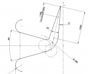
The horn of the tweeter I based this on (Klipsch K-85-K) has a horizontal angle of 90 degrees and vertical angle of 60 degrees; so I used a vertical angle of 15 degrees (60 / 4) to try to keep roughly the same load on the driver. When I first laid this out, it seemed to work out for a reasonable listening distance, sitting or standing; but now that I go back and look at it again, the horn would have to be placed much higher than I had thought.
Do you think it would work all right to increase the vertical angle of the horn after the bend, to, say, 20 or 30 degrees, but keep the 15 degree angle before the bend?
Thanks again for your input.
Attachments
The high frequency dispersion will still be determined by the initial angle even though the secondary portion of the horn expands.Do you think it would work all right to increase the vertical angle of the horn after the bend, to, say, 20 or 30 degrees, but keep the 15 degree angle before the bend?
Even if the horn provided 30 degree HF dispersion vertically, it would be a large jump from the 180+ degrees lower frequencies will spread to.
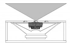
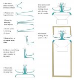
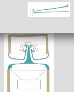
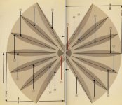
One way to provide around 180 degree vertical diffraction dispersion to 16 kHz would be to create a 360 degree distributed source horn (AKA Smith or DSH) with a vertical dimension of only 5/8" or so. The center would use a HF "deflector" as in your other designs, though the mid ports could simply enter within any of the horn "vanes".
The composite below gives a rough idea of what I described, less a few "vanes" top and bottom.
Art
Attachments
I'm trying to get my mind around this. Does this mean that the horn in this drawing would still only have 15 degrees of HF dispersion?The high frequency dispersion will still be determined by the initial angle even though the secondary portion of the horn expands.
Art
I would be happy with 30 degrees vertically at this point.Even if the horn provided 30 degree HF dispersion vertically, it would be a large jump from the 180+ degrees lower frequencies will spread to.
Art
Attachments
I was thinking a few years back about how easy it might be to make a Unity "Smith" horn, since the midranges would be entering from a horizontal flat surface. A "Unity Omni Smith" would seem do-able too (possibly an ignorant assumption?)
But previous experiments with omni designs, based on reflecting off of a cone, weren't very encouraging. The one I made sounded pretty good until it got at all close to any wall, then the sound would become very colored from the interference that happened from the large amount of near reflection. I don't have (and haven't really ever had) listening rooms with lots of available free space far out from walls.
But previous experiments with omni designs, based on reflecting off of a cone, weren't very encouraging. The one I made sounded pretty good until it got at all close to any wall, then the sound would become very colored from the interference that happened from the large amount of near reflection. I don't have (and haven't really ever had) listening rooms with lots of available free space far out from walls.
After thinking for a while about what you want to achieve, it occurred to me that the real synergy horns are designed to do exactly that. If you put the synergy horns in a ring, you'll get 360 degree (i.e., omnidirectional) sound with also well-controlled angular distribution in the vertical direction.
It seems to me that what makes the design efforts harder is the technical/engineering constraint you imposed on yourself, which is to use a single HF source coupled with some kind of waveguide to achieve the 360-degree distribution. If you can eliminate that constraint, and use multiple HF sources, then it might be simpler to obtain the omnidirectional sound with good vertical distribution. For instance, you can design and build 8 mini-synergy horns each with 90-degree horizontal coverage, and combine 4 of them as one channel. You can even combine the 4 mini-synergy horns into one unitary structure, and 3D-print that structure.
It seems to me that what makes the design efforts harder is the technical/engineering constraint you imposed on yourself, which is to use a single HF source coupled with some kind of waveguide to achieve the 360-degree distribution. If you can eliminate that constraint, and use multiple HF sources, then it might be simpler to obtain the omnidirectional sound with good vertical distribution. For instance, you can design and build 8 mini-synergy horns each with 90-degree horizontal coverage, and combine 4 of them as one channel. You can even combine the 4 mini-synergy horns into one unitary structure, and 3D-print that structure.
1) Yes, only around 15 degrees of dispersion. High frequencies behave pretty much like beams of light, you can trace the reflective rays from the source to visualize the pattern.1)I'm trying to get my mind around this. Does this mean that the horn in this drawing would still only have 15 degrees of HF dispersion?
2)I would be happy with 30 degrees vertically at this point.
2)A 360 x 30 degree horn is not omnidirectional, but if that's what you'd like :^)
- Home
- Loudspeakers
- Multi-Way
- omnnidirectional synergy horn?