Actually, it's the initial voltage that will be higher at turn on because the heater isn't drawing much current at first. As it draws more current, the voltage will drop.@FlaCharlie I assume the initial current through the resistor will be quite large, but go down as the filaments heat up. I was wondering what that curve looked like, and how much I should take it into account.
Just size the resistor based on the normal operating conditions of the tube and you'll be fine.
Ok!
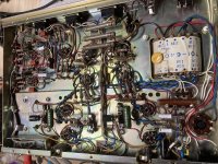
I changed the two last caps in the tone circuit. One of them was still fully functional! The other seemed to have a tiny, tiny, leak. I guess living next to the tubes keeps you dry..
I measured the mains voltage, 246V.. it's kind of high here, so no wonder the poor amp has been in such pain. Talked to the previous owner, he has 235V, and has had the unit on for 10 hours straight without issues.
Vak is about 150V (on the 12AX7s at least), so with that in mind, I guess a simple resistor to lower the heater voltage would do the trick?
Volume is identical on both channels. Right channel has a bit more noise on it, but not sure if it's audible. Will connect it to some music whenever I get the time.
Regarding the redplated tube.. I do have a used EL84 somewhere, could always try to substitute the redplated one with that. Have no idea what life it has lived, though, or even if it works.
Last edited:
I've just finished refurbishing this exact amplifier (all except the can caps -- they tested OK for now, and I'll probably get to replacing them in the next few months). I also didn't really touch the ceramics since they were so completely buried in the tone controls.
The volume pot was where I had the biggest problem -- very scratchy on both sides (I made the exact same mistake you did on the "why is one channel lower" -- thankfully I caught myself before I did anything too dramatic!) I took it apart and gave it a thorough scrubbing, and it's fine now.
I checked all the resistors, and I only needed to really change a couple.
Installed a three-prong power cord.
I'm on 230V, and was worried about the 110/220 problem. I checked my heaters when fully loaded and they were around 6.9V, which I thought was fine.
I replaced the EL84s with 6P14P-ERs. The old ones worked OK but were a little tired; the new ones should deal with the slightly higher heater voltage a bit better.
The top of my unit gets quite hot as well; I don't leave it on unattended!
Attachments
Interesting! 🙂 I immediately spot one difference - the 110/220v switch on my unit is a dummy. It's not connected to anything. Yours, however, seems to have a purpose. How do you like it so far?
You are incorrect about the heater voltage being "fine" at 6.9v. Your tubes will not last nearly as long as they would if you run them at the correct voltage. They'll last even longer if you run them a bit under 6.3v.I'm on 230V, and was worried about the 110/220 problem. I checked my heaters when fully loaded and they were around 6.9V, which I thought was fine.
I replaced the EL84s with 6P14P-ERs. The old ones worked OK but were a little tired; the new ones should deal with the slightly higher heater voltage a bit better.
Also, the Russian tubes you installed as replacements won't deal with the higher heater voltage any better than the others.
The 6P14Ps are rated at 5.7-7V on the heaters. They might not last 40 years, but they'll be OK. They're within the +10/-5% that is the normal operating range for 6.3V.
You can choose to run your amps lower if you like. If it had been 7V or over I would have probably taken more drastic measures.
I had nightmares about accidentally knocking the 110/220 switch during the repair! I should just hardwire it since it's unlikely that I'll be going to 120 land anytime soon.
I love it so far. I have it hooked up to a pair of Pioneer CS-51s which don't give much bass, but have a whole lot of character.
Last edited:
The 6P14Ps are rated at 5.7-7V on the heaters. They might not last 40 years, but they'll be OK. They're within the +10/-5% that is the normal operating range for 6.3V.
Is it +10%/-5%, or +5%/-10%? :O
I had nightmares about accidentally knocking the 110/220 switch during the repair! I should just hardwire it since it's unlikely that I'll be going to 120 land anytime soon.
Maybe that's why they just hardwired mine. Makes sense, that switch looks way too innocent 🙂
The 6P14Ps are rated at 5.7-7V on the heaters. They might not last 40 years, but they'll be OK. They're within the +10/-5% that is the normal operating range for 6.3V.
You can choose to run your amps lower if you like. If it had been 7V or over I would have probably taken more drastic measures.
The optimal operating range for a 6.3v tube is -10% (which is 5.7v) and +5% (which is 6.6v).Is it +10%/-5%, or +5%/-10%? :O
Obviously, we can all choose how we want to run our amps. And, at least these are not expensive tubes that are in short supply, so if a shorter tube life is acceptable to you, then run them higher.
But there is no advantage in doing so. The only result is more heat and shorter life. I prefer my amps to run cooler and have the tubes last longer.
And soldering in a couple of cheap wirewound dropping resistors is hardly a "drastic measure" as I see it.
I think it's usually +/- 10% -- 5.7V - 7V is 6.3V +/- 10%.
From Marvin Blencowe:
The Valve Wizard
"The heater voltage should be kept within +/-10% of its nominal value for optimum valve performance. For 6.3V heaters that means 5.7V to 6.9V, though it is even better to stay within +/-5% if you can (6V to 6.6V)."
From Marvin Blencowe:
The Valve Wizard
"The heater voltage should be kept within +/-10% of its nominal value for optimum valve performance. For 6.3V heaters that means 5.7V to 6.9V, though it is even better to stay within +/-5% if you can (6V to 6.6V)."
Well, he's talking about optimum performance. That simply means that the tube will operate according to spec when using that range of heater voltage.I think it's usually +/- 10% -- 5.7V - 7V is 6.3V +/- 10%.
From Marvin Blencowe:
The Valve Wizard
"The heater voltage should be kept within +/-10% of its nominal value for optimum valve performance. For 6.3V heaters that means 5.7V to 6.9V, though it is even better to stay within +/-5% if you can (6V to 6.6V)."
Performance is not the same thing as lifespan. And, as he points out, "it is even better to stay within +/- 5% if you can (6v to 6.6v)".
So using a heater voltage on the higher end of that range does not affect performance but it decreases the lifespan of the tube.
In contrast, using a heater voltage on the lower end of that range does not affect performance but it increases the lifespan of the tube.
The cost of the necessary resistors is less than $1 if you buy a few at a time. Individually, they're about 60 cents each. Compare that to the price of even a single replacement tube.
Your choice.
I think you'll find that the cost of the resistors is about $1, plus the $30-odd dollars for all the other components that you just happen to order so that you can get the free shipping. 
Ten 5w wirewounds for $3.79 shipped. That's 38 cents each.I think you'll find that the cost of the resistors is about $1, plus the $30-odd dollars for all the other components that you just happen to order so that you can get the free shipping.
10Pcs/Lot 5W Wirewound Cement Resistor Ceramic horizontal 0.1ohm -100Kohm | eBay
I'm not sure about their shipping policy in Europe (They do have warehouses around the world) but Digi-Key has a free shipping option in the US and Canada. No minimum order, no service charge.
Free Shipping On Parts Orders | Audiokarma Home Audio Stereo Discussion Forums
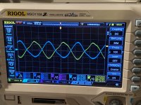
I tried putting in a 0.5ohms 10W resistor, filament voltage dropped to 5.9 and 5.8. That was obviously too low, as the first one gave a broken sine wave, and the second gave some weird signal a magnitude higher (10-15V or something). Is this typical behavior for a starving tube? Will try lower resistances tomorrow.
Edit: must note that rectifier was left untouched, so should be normal power levels elsewhere
Edit: must note that rectifier was left untouched, so should be normal power levels elsewhere
5.7 VAC should be OK, as it's within 10% of nominal. "Starvation" is an unlikely cause of trouble. FWIW, I like symmetry. Split the total dropping resistance into 2 equal parts and attach the parts to each end of the filament winding.
Yeah.. I think I broke something. Have a look at the scope. This is taken from the speaker output, with volume all the way down. Notice the vertical scale. 100mV left channel, 5V on right channel.
You see, yesterday I did something stupid. The amp was connected to a variac, which in turn was connected to an isolation transformer.
I had a brain fart and decided to connect my dac to the amp. The dac was NOT connected to the isolation transformer. Only audio on one channel. I switched something back and forth, and then both channels dead. I thought I blew my dac. But I think I perhaps have blown my tubes instead. Potential between normal ground and the isolated supply was 200V. Now, in my living room, I have old ungrounded gear. It's not that uncommon to have 120V between chassis and ground. So it stings if I touch my reel 2 reel tape recorder chassis and my TV at the same time. All levels out when audio cables are connected of course. But perhaps this was a bit too much for the amp frontend.
I'll order new tubes tomorrow. If I have been completely stupid, please tell me.
Attachments
By the fortune of the gods (and international shipping), my "new", long expected tube tester arrived in the mail yesterday. I'm still learning it, and some details are yet to reveal themselves to me (I'm relatively new to tubes, and the tester and manual is in French, which is not something I comprehend out of the box).
So I pulled out the 12AX7s and assumed they were bad. However, at least according to the tester, they passed almost all tests. Short circuit, insulation, emission and transconductance tests were fine for all sections. The only one that wasn't so fine was the gas leakage test. The vacuum was suboptimal.
The manual states for any leakage, the tube should be considered bad. However, I tried a Teslovac tube from a friend of mine, which "should" be pretty good, and it too had leakage (albeit not as much).
I tried lower filament voltage, and the tubes seemed weaker, but still functional. I guess I can try to replace the 12AX7s anyway, and see if it solves my problem. I'm pretty puzzled by that 50Khz signal, though. As I sit here and write, it occurs to me - could it be that the amplifier is picking up on a SMPS? The signal generator I use is also connected to the same isolation transformer. However, it's strange if it would propagate that wildly.
Is there anything else in the amplifier that might have gone bad? The circuit isn't especially complex.
BTW, I tested the power tubes (EL84) as well. They had some, but less leakage and were rather weak, but otherwise fine.
Vacuum valves are pretty much impervious to overvoltage shocks. Solid state widgets are, on the other hand, very fragile. Why do you assume that a valve has been damaged?
YOS,
Chris
YOS,
Chris
I assumed it since I couldn't see what else could have been wrong.
That said, there have been some changes to the setup that I should check and rule out. For example, I connected static 8 ohm loads instead of loudspeakers. I assumed it would be identical, but I see now (based on other threads here) that, in certain circumstances, it looks like it might alter the behaviour quite a lot.
Will check after office hours and come back with results.
@petertub, what could be the consequence of not replacing the tube? Suboptimal or catastrophic? Can I use the old one while waiting for spares to arrive?
Everything in this amp is original, so assume bias in ok in that regard?
Tube "testers" have ruined many fine tubes by users thinking that tubes are bad. The only real test for a tube is the circuit where it is located.By the fortune of the gods (and international shipping), my "new", long expected tube tester arrived in the mail yesterday. I'm still learning it, and some details are yet to reveal themselves to me (I'm relatively new to tubes, and the tester and manual is in French, which is not something I comprehend out of the box).
So I pulled out the 12AX7s and assumed they were bad. However, at least according to the tester, they passed almost all tests. Short circuit, insulation, emission and transconductance tests were fine for all sections. The only one that wasn't so fine was the gas leakage test. The vacuum was suboptimal.
The manual states for any leakage, the tube should be considered bad. However, I tried a Teslovac tube from a friend of mine, which "should" be pretty good, and it too had leakage (albeit not as much).
I tried lower filament voltage, and the tubes seemed weaker, but still functional. I guess I can try to replace the 12AX7s anyway, and see if it solves my problem. I'm pretty puzzled by that 50Khz signal, though. As I sit here and write, it occurs to me - could it be that the amplifier is picking up on a SMPS? The signal generator I use is also connected to the same isolation transformer. However, it's strange if it would propagate that wildly.
Is there anything else in the amplifier that might have gone bad? The circuit isn't especially complex.
BTW, I tested the power tubes (EL84) as well. They had some, but less leakage and were rather weak, but otherwise fine.
Testing a tube should be done at voltages and currents it is designed for ( noted in the info sheet for that tube) and not with the fizzly voltages most "testers" provide.
When proper conditions for a tube as established things like matching power tubes may be done. One device that does this repeatable is maximatcher.
- Home
- Amplifiers
- Tubes / Valves
- Old tube amp - do non-electrolytics need replacement?