ALL electrolytic caps. should be replaced. Those "boutique" 'lytics are well suited to the cathode resistor bypass role. Providing the value and WVDC are correct, put them to work.
Duly noted! As an apropos, there are some green caps in the picofarad range, I think they're micas. Can I assume they're good?
I ordered a bunch of 6P14P and 6N2P, Russian old stock. I'm new to buying tubes, so forking out the $$$ for some good ones are mentally challenging. There's a transconductance tester coming my way, so it seemed fitting. Hopefully they sound ok, and I can match up a couple of pairs (yes, I've gone a little nuts with the spending lately. But I find I really enjoy the point to point wiring, the smell, the way you can follow the circuit, the tubes themselves.. it's all a bit zen).
I ordered a bunch of 6P14P and 6N2P, Russian old stock. I'm new to buying tubes, so forking out the $$$ for some good ones are mentally challenging. There's a transconductance tester coming my way, so it seemed fitting. Hopefully they sound ok, and I can match up a couple of pairs (yes, I've gone a little nuts with the spending lately. But I find I really enjoy the point to point wiring, the smell, the way you can follow the circuit, the tubes themselves.. it's all a bit zen).
The Russian 6Π14Π (6p14p) is an EL84/6BQ5 equivalent, but it is (at best) mediocre. OTOH, the 6Π14Π-EB (6p14p-ev), AKA EL84M, is a 7189 equivalent that's pretty darned good. The current production JJ EL84 is better than decent and is not especially expensive.
The Russian 6H2Π (6n2p) substitutes electrically for the 12AX7/ECC83, but heater power rewiring is required. Again, as is frequently the case with Russian tubes, specimens with the EB (ev) suffix tend to be better performers.
The Russian 6H2Π (6n2p) substitutes electrically for the 12AX7/ECC83, but heater power rewiring is required. Again, as is frequently the case with Russian tubes, specimens with the EB (ev) suffix tend to be better performers.
Ceramic caps and mica caps tend to hold up well so they are generally not replaced when vintage gear is being restored.As an apropos, there are some green caps in the picofarad range, I think they're micas. Can I assume they're good?
But, again, you need to replace ALL the grey PIO caps in the amp, not just the ones that serve as coupling caps. And, as Eli says, also replace all the electrolytics.
Were you able to measure the heater voltages? If they're over ~6.6v or 6.7v, which I suspect they are, you need to take measures to alleviate the over-voltage.
Yes, I understood the 6N2P only had 6.3v heating, but since this amp has it as well I interpreted it as it would work as a drop-in. I do have some old Siemens ECC81/82 and E(81/82)CC lying around in a box, but I found conflicting advice on whether I could use them in place or not.
Regarding electrolytics - yes, I'll replace all, sorry if it came forth as otherwise. I do hesitate on changing the large filter caps yet, though, as I hoped to get my hands on an isolation tester to test them for leakage before I do it. I have to hollow them out and put new ones inside, since there's not enough space within the chassis. The new ones I ordered are pretty large, high ripple 105C caps.
6p14p-ev, got it. I guess I was a fool for thinking I could score something for a good price on eBay, you almost never get more than you pay for these days. However, to be honest, I'm happy with using low quality, scruffy tubes for a bit. I want to cherish the upgrades and have some fun 🙂
Yes, I understood the 6N2P only had 6.3v heating, but since this amp has it as well I interpreted it as it would work as a drop-in. I do have some old Siemens ECC81/82 and E(81/82)CC lying around in a box, but I found conflicting advice on whether I could use them in place or not.
ECC81 = 12AT7 and ECC82 = 12AU7. Good tubes to have available, but they are not drop in replacements for the 12AX7/ECC83.
When you heat 1 of the 12A_7 bunch with 6.3 VAC, pins 4 and 5 are bridged. A wire is connected to the bridged pins and the 2nd wire is connected to pin 9.
You apply, with 2 separate wires, 6.3 VAC to pins 4 and 5 of the 6H2Π (6n2p). Pin 9 gets connected to chassis ground.
Regarding electrolytics - yes, I'll replace all, sorry if it came forth as otherwise. I do hesitate on changing the large filter caps yet, though, as I hoped to get my hands on an isolation tester to test them for leakage before I do it. I have to hollow them out and put new ones inside, since there's not enough space within the chassis. The new ones I ordered are pretty large, high ripple 105C caps.
Stuffing new, modern, parts into the OEM cap. cans has been done (successfully) many times. An alternate and (IMO) less fussy method is to clamp mount modern parts in the openings occupied by the OEM "twistlok" stuff. Clamp mounting allows for successful use of 85o C. rated parts, as they are out in the ambient air and can convection cool.
Looking at the pic you posted earlier, there is plenty of room to mount replacement caps underneath, as long as the chassis is deep enough, which it seems to be. There are even existing holes and/or screws that can be used to mount terminal strips for the replacement caps.Regarding electrolytics - yes, I'll replace all, sorry if it came forth as otherwise. I do hesitate on changing the large filter caps yet, though, as I hoped to get my hands on an isolation tester to test them for leakage before I do it. I have to hollow them out and put new ones inside, since there's not enough space within the chassis. The new ones I ordered are pretty large, high ripple 105C caps.
@wiseoldtech, I understand a lot of people do, but do I risk anything by still using it until I get replacements? It didn't redplate hard, just slightly. If I keep it under observation, and it doesn't redplate again, isn't it ok?
@wiseoldtech, I understand a lot of people do, but do I risk anything by still using it until I get replacements? It didn't redplate hard, just slightly. If I keep it under observation, and it doesn't redplate again, isn't it ok?
The choice is up to you.
As a long-time serice tech, I find that once a tube redplates, the coating on the plate is now compromised/damaged, as well as the internal grids, and the tube's life and performance is shortened.
My tube testers confirm the difference in emission levels between good tubes and one that have even slightly redplated.
Also, being that way, it's not balanced with its other tube in push pull use.
I prefer to stay on the safe side of things that way, and just replace the tube or both if a PP pair.
Well you ignored the suggestion that you should replace all the gray caps. As a result, you now need new tubes.do I risk anything by still using it until I get replacements? It didn't redplate hard, just slightly. If I keep it under observation, and it doesn't redplate again, isn't it ok?
Now you're asking if it's OK to run the amp with damaged tubes? 🙄
Well you ignored the suggestion that you should replace all the gray caps. As a result, you now need new tubes.
Now you're asking if it's OK to run the amp with damaged tubes? 🙄
Indeed.
Anything with those types of caps isn't powered up until they're replaced, tubes have been tested, and filters replaced.
I've done many customer units where I can't afford to play around with guessing things, and taking chances.
Well you ignored the suggestion that you should replace all the gray caps. As a result, you now need new tubes.
Now you're asking if it's OK to run the amp with damaged tubes? 🙄
Yes 😀
So I replaced all the capacitors - some quick cowboy soldering, but the plan is for the coupling caps to be replaced yet again later, whenever I get the old PIO things.
I double checked, and yes, you were very right, I had room for the new filter caps underneath. Somehow, in my fatherly, sleep deprived state (three kids..
 ), I thought I had to solder the new ones right underneath / next to the old cans. Then I realized that there are long wires going from all around the chassis, so proximity isn't so important after all..
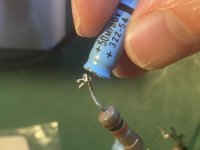
Now, desoldering the electrolytics was pretty time consuming. Those who assembled it have twisted component wires around each other, like those shown in the attached picture. I wish I was able to do it like that. Did they have some special tool? My work is way uglier, no matter how hard I try!
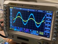
Fired up the puppy, and everything is nice, except the right channel volume is way lower than the left (see pic). Could it be because of the worn tube? Again, do I risk anything by having it on and probing around with my multimeter, except that the tube stops working?
Hum and noise is very low, if I crank it all up I can hear it -- but if I had any audio going on, I would break my ears I guess.. it's only a 15W amp, but I'm running them on a pair of bookshelf speakers (B&W DM601).
Oh, and with regards to heater voltage and 240V.. it probably comes at no surprise that the heater voltage is about 10% higher, resting at 6.9V. How will this affect tube life? And, apart from making some buck transformer to lower the input voltage, are there any tricks I can do to "convert" it to 240V? Will the increased B+ be any issue, or is it mostly the heaters I should worry about?
Thank you for your patience, and sorry for all the messy questions!
EDIT: I see I missed a couple of caps coupled to the tone controls, on the other side of the chassis. That'll have to be for tomorrow (it's evening here now).
EDIT 2: I realized why the volume was so different. Maybe you do as well. Time to go to bed (or at least, NOT touch this thing any more until tomorrow!)
Attachments

Last edited:
I've ordered both an autotransformer and a selection of dropping resistors. I was thinking, if the plate voltage is within a comfortable range, I can just reduce the filament voltage. If not, I'll use the transformer. Would be very nice to avoid it, though.
But with regards to dropping resistors and wattage rating -- would a 5W do? How quickly do the heater filaments increase their resistance? Would the inrush current fry my resistor? Transformer heating taps are rated 2.2 and 2.5A @ 6.3V.
Also, would running the heaters a bit lower cause any issues? For example, 6V instead of 6.3V. Would it save tube life?
Last edited:
I just don't get why a capacitor with an inferior dielectric like paper should »sound better« than one that involves one of the best known dielectrics - if a capacitor does sound at all. I severly suppose that those PIO capacitors should be named more precisely PISO - paper in snake oil.
Best regrds!
It's funny, I said something very similar on the DIYA FB page, very recently
The 6.3 VAC value for tube heaters is nominal. If the actual value is within -10% to +5% of nominal, you're fine.
If one channel is louder than the other, swap tubes side to side and see if it follows the tubes. In a PP amp a channel will function even with only one output tube, so it could be the tube is dead.I've ordered both an autotransformer and a selection of dropping resistors. I was thinking, if the plate voltage is within a comfortable range, I can just reduce the filament voltage. If not, I'll use the transformer. Would be very nice to avoid it, though.
But with regards to dropping resistors and wattage rating -- would a 5W do? How quickly do the heater filaments increase their resistance? Would the inrush current fry my resistor? Transformer heating taps are rated 2.2 and 2.5A @ 6.3V.
Also, would running the heaters a bit lower cause any issues? For example, 6V instead of 6.3V. Would it save tube life?
If the heaters are running more than ~5% over nominal (~6.6v) tube life will be reduced and the higher it goes the faster they'll die. Running them on the low side will increase their life.
Other voltages are generally not as critical IF none of the other parts are being run close to the edge. You should check to make sure that none of the lytics are close to their voltage rating and that none of the resistors are dissipating too much.
Resistors can be added to the heater supplies to reduce the voltage. Use Ohm's Law to calculate the value needed to obtain the correct voltage drop. This needs to be based on the actual current draw of the tubes (taken from the data sheet), not from the maximum rating of the winding. Size the resistor so that its wattage rating is at least 3x actual dissipation. I prefer derating by 5x, 3x should be the minimum.
- Home
- Amplifiers
- Tubes / Valves
- Old tube amp - do non-electrolytics need replacement?