Just got a big dirt cheap tranny.
I was told it has 350-0-350 (450 watts), 5V secondary, 6.3 V secondary @ 5 amps.
No markings and confused with which is the primary.
On 1 side it has 2 outputs:
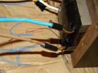
1st output: 2 very thick wires and 1 very fine wire. 1.2 ohms between all of them. If this is the primary shouldn't it have a higher resistance? And what is the thin wire for?
2nd output: 2 thin wires with 5.6 ohms resistance (maybe the 6.3V?)
On the other side:
1st output: 2 thick wires with a 1.2 resistance (maybe the 5V)
2nd output: 3 very thich wires, 62 ohms between the 2 and 124 ohms between the 3rd (i assume this is the 350-0-350).
What's the best way to test this? I was informed it was working fine.
I was told it has 350-0-350 (450 watts), 5V secondary, 6.3 V secondary @ 5 amps.
No markings and confused with which is the primary.
On 1 side it has 2 outputs:
1st output: 2 very thick wires and 1 very fine wire. 1.2 ohms between all of them. If this is the primary shouldn't it have a higher resistance? And what is the thin wire for?
2nd output: 2 thin wires with 5.6 ohms resistance (maybe the 6.3V?)
On the other side:
1st output: 2 thick wires with a 1.2 resistance (maybe the 5V)
2nd output: 3 very thich wires, 62 ohms between the 2 and 124 ohms between the 3rd (i assume this is the 350-0-350).
What's the best way to test this? I was informed it was working fine.
What's the best way to test this? I was informed it was working fine.
Get yourself a 10 ~ 12 VAC supply. Dig through your box of old wall warts; chances are you will find one that will work. Take your best guess as to which winding is primary, and connect it to that. Measure what comes out of each of the other windings. Now scale the results to calculate what you'd get if you had connected line voltage (120 VAC) instead of your test voltage (10~12 VAC).
The primary winding is often black, white, or blue. High voltage secondary is often red or orange. Heater windings are typically green, yellow, or brown. Good luck!
Was just thinking of the same thing. Got an old switchable ac wall outlet. I'll give this a go.
Also taking the casing apart found another small very fine wire coming from the second output on the first side. Strange. maybe the 5v and 6v windings have CT.
Also taking the casing apart found another small very fine wire coming from the second output on the first side. Strange. maybe the 5v and 6v windings have CT.
I would think that side 1 output 1 would be the 6.3 volt filiment winding with a center tap ground. The second winding on side 1 is most likely the primary. On side 2 output 1 is most likely the 5 volt winding for a tube rectifier and the # 2 output is the high voltage winding. The low voltage high current windings are going to be the lower in resistance windings. The very fine wire you found inside may be an internal shield ground connection between the primary and the other windings.
I would use the transformer test suggested by Ty.
Good luck
BZ
I would use the transformer test suggested by Ty.
Good luck
BZ
Just tried it first with the 12v and now with 220.
Yes 1st side is the primary and next to it reads 6v (reads ~6-7 without load).
2nd side I'm getting 440V without load and the other secondary wavering around 5V.
It's buzzing quite a bit.
Is this normal with these giant (about 10-12 kilos, 4-5 inches wide) transformers or is indicating a problem?
Yes 1st side is the primary and next to it reads 6v (reads ~6-7 without load).
2nd side I'm getting 440V without load and the other secondary wavering around 5V.
It's buzzing quite a bit.
Is this normal with these giant (about 10-12 kilos, 4-5 inches wide) transformers or is indicating a problem?
Taking one of those old transformers apart causes you to break the varnish that coats the windings, core and cover. One of the main reasons to varnish dip transformers was to keep them from buzzing. The other is to seal them from moisture. Make sure to replace the covers and tighten the bolts, that may help the buzzing because it clamps the laminated core and its the core that buzzes most of the time.
BZ
BZ
good to know.
yes I have stripped the wires, cleaned the rust of the laminates front and sides and will repaint the end covers (not shown in the photos as they are removed).
So once the bolts are replaced and tightened maybe I have less buzzing.
Mind you I have a big Carver SS power amp and that thing vibrates like a train.
See the pics, I found these fine wires between the 6 and 5 v secondaries.
Can I just tape these up and leave them?
Attachments
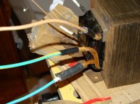
Are they connected to any of the windings? Check with ohm meter. If not connected to windings they may be ground for interwinding shield. Was the end of the fine wire traped under the end bell/cover? That would be an indication that they are interwinding shield ground.
BZ
BZ
Last edited:
When you go to replace the endbells make absolutely certain you have replaced the isolation washers, usually a fiber washer and paper tubes from the old days. Even better go to one of the modern hardware stores and look in their bearings section for molded nylon parts with a washer and barrel that just fit over the bolts. Use these T barrel items as isolation. Put them under the head of the bolt with the barrel sticking down through the end bell and core bolt hole, assuming you have corner bolts. Side bolted end bells are just as impo0rtant in terms of insulation of the bolt head from the end bell metal.
Doing this will avoid an eventual, or sudden core short, resultant high current in the primary, potential fire, lot's of evil smelling smoke that will last for weeks and of course, transformer death.
Doing this will avoid an eventual, or sudden core short, resultant high current in the primary, potential fire, lot's of evil smelling smoke that will last for weeks and of course, transformer death.
Are they connected to any of the windings? Check with ohm meter. If not connected to windings they may be ground for interwinding shield. Was the end of the fine wire traped under the end bell/cover?
One of them was under the end bell/cover. The other no, it had an old perished cable cover but only at the beginning.
I did get a reading on the one with the old cover so I assume this is the CT.
So if the other has no reading it's the internal shielding ground and this must be pressed between the bell cover once replaced.
When you go to replace the endbells make absolutely certain you have replaced the isolation washers, usually a fiber washer and paper tubes from the old days. Even better go to one of the modern hardware stores and look in their bearings section for molded nylon parts with a washer and barrel that just fit over the bolts. Use these T barrel items as isolation. Put them under the head of the bolt with the barrel sticking down through the end bell and core bolt hole, assuming you have corner bolts. Side bolted end bells are just as impo0rtant in terms of insulation of the bolt head from the end bell metal.
The end bell/covers were bolted directly to the laminate core. Should there be insulation between the end bell and laminate?
If there is no insulation what use is insulating the corner bolts if you don't mind me asking?
I'm understanding now the insulation washers need to go between the end bell/cover and laminate core through the bolts no? So there is no contact between the end cover and laminate?
BUT according to the comment above the internal shield wire was compressed between the bell cover and laminate.
I'm a little confused now.
Thanks in advance for your advice.
It is the bolts themselves which must be insulated from the covers in order not to form a shorted circuited turn.
Sorry, "shorted circuited" -jibberish or a new electrical term? Please be extremely careful,I REALLY don't like the look of that transformer.
Please be extremely careful,I REALLY don't like the look of that transformer
now you've got me scared.
What makes you say that? The state of the original cables?
I made sure I had a small fuse on the primary before I plugged it in. Maybe a bulb across would be a good idea also and isolated stand offs.
Indeed it is the state of the cables that bothers me. If you have it fused properly and hard earthed then you can relax. I must say that I always try to salvage stuff within reason myself. I assume you are totally clear now on the shorted turn matter;it is the usual mode of destruction of toroids when both ends of the securing bolt are allowed to touch the chassis.
The end bell/covers were bolted directly to the laminate core. Should there be insulation between the end bell and laminate?
If there is no insulation what use is insulating the corner bolts if you don't mind me asking?
I'm understanding now the insulation washers need to go between the end bell/cover and laminate core through the bolts no? So there is no contact between the end cover and laminate?
BUT according to the comment above the internal shield wire was compressed between the bell cover and laminate.
I'm a little confused now.
Nope, the washer / T barrel insulator goes on the bolt right under the bolt head. If it is just a washer then there must also be a soda straw like sleeve slipped over the bolt body. This entire event slips into the corner hole, with both end bells already in place. You are insulating the bolt head and body from the entire transformer. It is OK for the nut end of the bolt to not be insulated. The end bells need to be right up against the core, no insulation there, at all.
This is done to keep the lamination stack from shorting across the stack. Lamination's are thin so they will readily accept electromotive force. They are insulated from each other with an oxide coating, to keep them from shorting to each other. This is done to limit the inductive excursion during the first half wave of an AC EMF signal from the primary winding. If there was only a solid block of steel, no laminations, the EMF charging current would need to be very high to overcome the reluctance of the solid block of steel to accept the EMF charge and then the block of steel would exhibit inductive run away, causing a huge current to be induced in the primary with an attendant huge current draw. Subsequent fire is assured.
If it is just a washer then there must also be a soda straw like sleeve slipped over the bolt body. This entire event slips into the corner hole, with both end bells already in place. You are insulating the bolt head and body from the entire transformer. It is OK for the nut end of the bolt to not be insulated. The end bells need to be right up against the core, no insulation there, at all.
No soda straw like sleeve evident over the bolt. Just a plain bolt fixed right through the laminate core.
So from what I understand the 4 bolts holding it all together needs to be totally isolated from the laminates and end bell?
Thanks
At least one end of the bolt and the threaded portion of the bolt, must be isolated. A molded nylon T barrel bearing/washer of the appropriate size, under the bolt head, with the barrel extending over part of the threads is adequate, as this will center the bolt in the hole and provide isolation. Otherwise you need a fiber washer and a soda straw.
Whomever had this transformer before you was just damn lucky.
Otherwise, the transformer looks to be decently well made. Pretty typical commercial unit. The woven fiberglass sleeving should have a clear acrylic coating over it, at least for the B+ leads and primary leads. If not you might want to place shrink tube over the part that actually makes contact with the end bells just for safety.
think i have some plastic tubing that will fit the bill just right. old tubing from telephone cabling. I used the thin wires for some contruction work in my amps.
and some old fiber or plastic washers I'm sure I have. fiber for sure as I just serviced my dellorto carbs and changed them all.
and some old fiber or plastic washers I'm sure I have. fiber for sure as I just serviced my dellorto carbs and changed them all.
Now I'm going to respray the end bells.
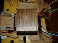
In regards to the laminate core, I have cleaned the surface with a dremel and fine wire brush to remove the rust. Looking good now.
Also did the coloured cable connections with better heat shrink tubing.
Can I paint this laminate core? Maybe a coat of varnish only? Or the black paint and then covered in varnish?
The plastic tube should be just fine. Please make it long enough that it is just slightly compressed when the end bells are snugged up by the nuts.
As for mauling the thing with Dremel and wire brush, try not to do any work on the core plate edges and anything you do, look at under at least a 7 power mag. You need to assure that you have'nt allowed metal from one laminate edge to touch another laminate edge. By this I mean metal that has been removed except for a small burr that has been inadvertently bent over to touch another bur. What you do on the face of the laminations, adjacent to the bobbin is not of electromagnetic importance. Painting with any good acrylic or enamel based paint should be just fine. Lacquer based paints may react with whatever is still on the surfaces and any that runs onto the coil may have the same effect.
As for mauling the thing with Dremel and wire brush, try not to do any work on the core plate edges and anything you do, look at under at least a 7 power mag. You need to assure that you have'nt allowed metal from one laminate edge to touch another laminate edge. By this I mean metal that has been removed except for a small burr that has been inadvertently bent over to touch another bur. What you do on the face of the laminations, adjacent to the bobbin is not of electromagnetic importance. Painting with any good acrylic or enamel based paint should be just fine. Lacquer based paints may react with whatever is still on the surfaces and any that runs onto the coil may have the same effect.
- Status
- Not open for further replies.
- Home
- Amplifiers
- Tubes / Valves
- Old tranny - confused with windings