To use the DAC-END with tube, I connected the jumper on 1 and 2. Is it correct ? The tubes should invert. So the signal goes from pin 26 of the CS8414 to pin 10 of the AD1865.
In this case what is the 74HC04 doing ?
Thanks,
Davide
In this case what is the 74HC04 doing ?
Thanks,
Davide
To use the DAC-END with tube, I connected the jumper on 1 and 2. Is it correct ?
no correct!
What is the sound ???
I got the mine playing tonight ! Very impressed by the sound.
I have around 5.3 V on the input of the DAC. Is that enought ? I cannot raise it more.
Good project !! I like all these little modules to play around.
Davide
Hi, Good work!
Please post some pictures 🙂
Regarding 5.3V..
What is your resistor value for R13 on salas shunt?
Also measure gate - source on the last mosfet. It should read around 4V. If not you need to lower the R13 resistor value.
Best Regards
David
Last edited:
I got my working just now, very nice sound. I still have to replace few components with audio grade. I will try mods sometime next week.
Very nice!
I see you have Wima on the output of I/V. how do you like them?
I tried RIFA PHE426 1µf and liked it very much.
You have some good time ahead trying different mods 🙂
Best Regards
David
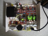
This is a picture of the working prototype.
I used one transformer with two secondaries for +-5V one for +5V.
The black small one is a 5H choke and the black big one is the power transformer for HV. this is temporary.
Still did not understand the right position for the jumper, and how many regulators and filament supply I should use.
BR,
Davide
Attachments
This is a picture of the working prototype.
Still did not understand the right position for the jumper, and how many regulators and filament supply I should use.
HI,
Thanks for the picture 🙂
If you want the signal to be in phase you need to connect a jumper between 2 and 3. If not. Use 1 and 2.
Your prototype seems to be complete to me.
Nice work with the shunt reg for the tube stage!
Best Regards
David
You mean the phase out of the DAC-END circuit or out of the Tube stage ?
The tube stage itself inverts.
D.
The tube stage itself inverts.
D.
So I have R13=10 ohm
VgsQ16=3.3 V
R7=33 ohm
VgsQ10=3.6 V
R1=33 ohm
Vgs=3.8 V
I have available resistors of 27 ohm, 22 ohm , 8.2 ohm and 6.8 ohm. Do you think I should replace them ?
Are the heatsink really needed ? It's not that hot.
D.
VgsQ16=3.3 V
R7=33 ohm
VgsQ10=3.6 V
R1=33 ohm
Vgs=3.8 V
I have available resistors of 27 ohm, 22 ohm , 8.2 ohm and 6.8 ohm. Do you think I should replace them ?
Are the heatsink really needed ? It's not that hot.
D.
it depends on the current through the resistor, tolerances count for a lot here.
Mine isnt that hot with 11r, i could get away with no heatsink.
Mine isnt that hot with 11r, i could get away with no heatsink.
Now I have 8.2 27 27
The Vgs differences increased, now I have 3.9 V, but not the output voltages. Could it be that my leds are forcing a too high reference voltages ?
Davide
The Vgs differences increased, now I have 3.9 V, but not the output voltages. Could it be that my leds are forcing a too high reference voltages ?
Davide
it could be.
I wouldnt worry about it, once i hit about 5.3v, on the scope the output after the tl431 looks the same as those on 5.6v.
I wouldnt worry about it, once i hit about 5.3v, on the scope the output after the tl431 looks the same as those on 5.6v.
Very nice!
I see you have Wima on the output of I/V. how do you like them?
I tried RIFA PHE426 1µf and liked it very much.
You have some good time ahead trying different mods 🙂
Best Regards
David
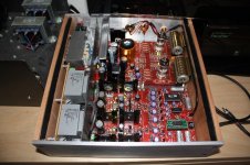
I like them, I'm surprise how well it plays. I want to try some Russian OTK PIO caps later on. I did A-B with my Y2 DAC and found that when using terminal blocks L input channel on I/V is R and R is L. Photo on my previous post is correct.
I also had jumper set to 1-2, I changed to 2-3.
I'm planning to use a custom made 80VA toroidal trafo with 3x12V. Will it be any problem for the Sallas reg or is better to use one 2x12V trafo for the +5V,-5V and one 1x12v for the +5V?
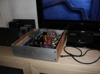
I thought I should post some pictures of my build.
I did as Adamus recomended and removed the inductors and added the "led-mod". I listened to the DAC standard and to me these mods made it suit my ears better.
I tried both E182CC and 5687 and prefer the E182CC. Also use Sprauge Hyrel Q 1µf output caps.
To me this DAC easily beat my old parallell tda1543 dac.
Thanks Quang hao, Andrea and Salas. Also thanks to everyone who contributed in this thread!
Attachments

NOS E182CC Mullard
I got my DacEnd up and running yesterday. I had day off today and I'm playing music all day. I'm enjoying very much. I'm running with GE JAN 5687WB, I want to try E182CC. Where preferably in US I can get E182CC for reasonable price ?
I found on ebay:
"6N6P Double Triode, It is direct replacement of ECC99,E182CC"
but it's not, correct ?
- Status
- Not open for further replies.
- Home
- More Vendors...
- Quanghao Audio Design
- OLD THREAD DAC End by Andrea Ciuffoli