Did you ever measure the 12Pi V2 to see if it conformed to the simulation, filling in the 2 dB dip around 45 Hz ?
Yes, and it does. In fact, I measured several configurations having a variety of front/rear chamber sizes. These are all shown in the threads linked in the 12Pi hornsub page. There's a lot of information there, a sort of experienent in a variety of things, all shown as they unfolded. There are two different cooling systems (one of which I patented), a variety of horn configurations and then finally as it came together and the basic shape was set, a fine-tuning of the front and rear chamber sizes.
There is an optimum size for response smoothness and another (slightly different) optimum size for lowest excursion. Of course, the small end of the scale is tough to do physically, because it requires shape conformity around the driver, itself. So I used a handful of arrangements of chamber size and internal filler panels to set the sizes, balancing the priorities of manufacturing simplicity and optimizing performance (being something of a perfectionist). These chamber size differences are the only diferences between Versions 1 and 2 (and the prototype, sort of Version Zero).
Last edited:
Wayne,Yes, and it does. In fact, I measured several configurations having a variety of front/rear chamber sizes. These are all shown in the threads linked in the 12Pi hornsub page. There's a lot of information there, a sort of experienent in a variety of things, all shown as they unfolded.
As you say, a lot of information there, after an hour searching yesterday did not find any measurement of the 12Pi V2, only a simulation.
Your posting an overlay of the measured responses of the different versions here would be interesting to see.
Art
Art this link has the info you need.
PiSpeakers Forum - 12? basshorn subwoofer - the best yet! - Wayne Parham, October 04, 2007 at 15:33:34
The version with the "dip" had a rear chamber size of 20 liters (dont know if this is before or after driver displacement). If this is before driver displacement, this makes it about the same size as the lab horn rear chamber (and thus there is identical dips). wayne notes that increasing the rear chamber to 27 liters (again, dont know if this is before or after driver displacement) basically eliminates the dip .
Those are the V1/ V2 Hornresp simulations I saw yesterday, I was looking for an actual measurement of V2 to see how it compares to the cabs measured in '05, '06, and '07.Art this link has the info you need.
Sims are helpful, but I like to see the difference between them and "as built", what we listen to.
Art
Last edited:
I personally cannot find any measurements other than the V1 measurments (which feature both the dip, and a startling 3 db droop in sensitivity below 70hz).
This end loaded vs offset issue was a big problem 15 years ago, everyone was doing it. Parham did the same thing in his Hornresp study of the Labhorn too, ...
PiSpeakers Forum - 12 ? observations and comparisons with other designs - Wayne Parham, July 08, 2005 at 03:53:47
That's the Labhorn study I was talking about, first and third graphs on this page. Haven't seen this page in years, but as I said, everything back then was simulated as end loaded but folded as offset, and it led to a saddle in the measured response that was not present (or worse than) in the simulation. Hornresp couldn't do offset back then, only Akabak could.
Anyway, it's interesting to see that he input the Labhorn rear chamber at 34 liters, which is much worse than the 40 that I showed. If it really is 34 liters when loaded with drivers it's about 32 percent too small.
Yet the measured response of the 12Pi and the Labhorn both show the same 2 dB dip.Anyway, it's interesting to see that he input the Labhorn rear chamber at 34 liters, which is much worse than the 40 that I showed. If it really is 34 liters when loaded with drivers it's about 32 percent too small.
Will be interesting if Wayne will post a measurement of the V2 and see what difference there is.
Yet the measured response of the 12Pi and the Labhorn both show the same 2 dB dip.
I don't know anything about the 12Pi other than what I see on that page so I can't comment on it, other than the fact that it can't possibly be end loaded but it's simulated as such.
Again, the point here is that nobody was properly simulating offset driver horns back then and there were consequences. And again, if you accurately build what you simulated the measured results should be very close to the simulation, there's shouldn't be any big deviations.
Last edited:
The Lab Horn throat is a pair of parallel baffles with an enclosed slot (throat chamber), the slot exit (7.5" on the thin dimension x approx 12") is smaller than the other end of the slot.Again, the point here is that nobody was properly simulating offset driver horns back then and there were consequences.
As such, it fits about as well to an end fire horn with a VTC as an offset driver model, other than a possible (very) minor path length difference.
At any rate, Wayne's old Lab 12 model conforms to the as built measurement you posted pretty well, and although his wider push pull 12Pi model adjusted front and back chamber volume from the original, the response of it is still quite similar, other than a slight increase in level due to the increased cabinet volume, and reduced even order distortion due to push pull loading.
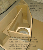
The sonotube in the LabHorn example below was not recommended, it would reduce horn volume further from the original plan, reducing LF output.
Attachments
As such, it fits about as well to an end fire horn with a VTC as an offset driver model, other than a possible (very) minor path length difference.
Post 27 shows very clearly the effect of simulating as end loaded but folding as offset. It shows 32 cm offset which is too much offset but even a 6 inch offset has consequences. If you don't build what you simulated the measurements won't match the sim.
Anyway, I think that's enough, I've repeated that last sentence at least a dozen times now, anyone reading this can take that for what it's worth or leave it. This issue is exactly why some people refuse to trust simulations, there are examples everywhere of people putting whatever they want into a sim and then building something completely different and blaming the software.
Last edited:
VTC= Volume of Throat Chamber.I don't know what this sentence means and I don't know what VTC is (although I think the TC part is throat chamber).
Anyway, post 27 shows very clearly the effect of simulating as end loaded but folding as offset.
Offset horn VTC is usually only the volume enclosed between the driver and the horn throat baffle, the concave portion of the driver cone plus the baffle cut out thickness.
The Labhorn is built with a slot throat with a throat chamber volume which includes the concave portion of the cones plus the baffle cut outs, and an additional volume roughly 12.5" x 12.5" x 7.5". That enclosed volume feeds in to the first portion of the horn.
That VTC does not translate specifically as part of an offset horn path length.
You seem to think it does, so let's just agree to disagree.
That VTC does not translate specifically as part of an offset horn path length.
You seem to think it does, so let's just agree to disagree.
All the simulations and measurements of both the Labhorn and 12Pi agree with me, and nobody simulates offset driver horns or tapped horns as end loaded anymore since Hornresp can now simulate them properly because it's clearly not accurate.
I'm happy to agree to disagree though, this is going nowhere. If you think you can simulate as end loaded and build something with the driver offset anywhere you like along the horn flare, good luck with that, but your simulations won't match your measurements. This wasn't well known in 2000 but I'm kind of shocked that this needs to be pointed out in 2014, but whatever.
Last edited:
Guys, it's been a while since I've read a thread like this. It's so funny to see people get so worked up about something they love and *almost* agree about...
The Lab horn was emerging as I started getting interested in horns. I was living with my parents and my room was about 12 m^2... It never happened. Now I'm married and have a sealed box subwoofer discretely in a corner, sigh.
The Lab horn was emerging as I started getting interested in horns. I was living with my parents and my room was about 12 m^2... It never happened. Now I'm married and have a sealed box subwoofer discretely in a corner, sigh.
Hi Y'all,
MaVo posted a collection of Danley posts pertaining to the LabHorn in the Collaborative TH Thread, Post #3273:
http://www.diyaudio.com/forums/subwoofers/97674-collaborative-tapped-horn-project-328.html
Otherwise I second Ivo's sentiment.
Regards,
MaVo posted a collection of Danley posts pertaining to the LabHorn in the Collaborative TH Thread, Post #3273:
http://www.diyaudio.com/forums/subwoofers/97674-collaborative-tapped-horn-project-328.html
Otherwise I second Ivo's sentiment.
Regards,

funny you bring this up.though may change towards the magnet moving in a fixed coil as amperage and excursion demands increase.
Art
i did some experiments using a moving magnet,it works.
the problem is to get radial magnetised magnets with the right lenght and thickness.
yes you can get the made in china 1000 pcs ,but thats a bit to much for an experiment.🙁
erik
The price of Neo is going to have to come back down. Really down - if we're going to be rolling our own drivers.
But wouldn't making the coils out of copper tubing and pumping LN2 (or at least chilled water) thru them be cool? Power compression? What power compression???
But wouldn't making the coils out of copper tubing and pumping LN2 (or at least chilled water) thru them be cool? Power compression? What power compression???
Moving magnets can work although there is an advantage using them as the moving part if they rotate.
The distribution of mass and torque in a rotary system follows different rules than a rectilinear system. In the old days, my job was developing transducers for acoustic levitation but on the side, I also designed them for what I wanted , loudspeakers.
Aside from the Servodrive woofers which used a rotary servomotor and conventional piston radiators, there were some other rotary speakers too. Here are a couple moving magnet motors which worked as loudspeakers, one was licensed to a company in car audio but was produced in a new “wonder plastic” which ultimately was not strong enough to make a motor housing out of. The cyclone below also used a rotary radiator system.
We had made “large” version of that one which had the displacement of 6X 18 inch woofers and these were installed for sound cancelation around the circumference of a 20 foot diameter fans at the Redondo Beach power plant in California. These had a large “wire in gap”, overhung moving magnet motor like he patent shows in fig 1.
When we built these, I remember I had a nightmare the night before assembling the first motor, it used 2pc of neo, that were 2X2X1 inch, poled through the 2 inch and these were epoxy’d into an aluminum rotor. The solution for assembly (the two magnets do not want to sit next to each other) came in that same dream and worked like a dream too.
We plugged the coil parts into an outlet to heat up the wire and set the potting compound. I am not sure if they had all of it installed at the point the earthquake hit and took the plant off line permanently. Oh well, it wasn’t the first or last time a huge amount of work went down the drain. I still have one of the big ones though, waiting for a time to resurrect the approach.
https://www.google.com/patents/EP06...rm9GsOR2QW_-IDwBg&sqi=2&pjf=1&ved=0CF0Q6AEwBg
http://download.phoenixphorum.com/TechSupport/Cyclone/23.jpg
http://forums.trinituner.com/upload/data/9e/phoenix-gold-cyclone.jpg
What one needs to do is figure out the moving mass, radiator area and motor figure of merit to see where in the continuum of possible T&S parameters one ends up.
I always sort of felt like making the transducers or new kinds of transducers was sort of the final frontier in DIY. When we run out of things to do with stock devices there are a few things which may be revived in a new form, there are a number of things one can do now, that one couldn’t then..
Best,
Tom
Tom, you guys had a thing that was like a two-part Japanese room screen, 80-18k Hz. The whole thing flapped a few millimeters. Is that related to the first patent?
- Home
- Loudspeakers
- Subwoofers
- Old School Horn vs Modern Vented Box