Hi
Hey just a guy, the volume wasn’t a mistake, the box dimensions (all truck pack, designed to work in a group of 6) and the low corner were picked by the group.
I gave Jerry the driver parameters that would be “perfect” and after a couple rounds, we had a driver that worked pretty well.
There weren’t any drivers that had he mass density back then to do this although the BT-7 driver had 2X15 inch radiators (and much more motor strength and mass).
The whole project came about on PSW when there were many threads about a “wonder sub” and people talking about wanting to build a bunch of W bins.
I thought it would be fun to design a DIY project that would stomp the larger “wonder sub” and show he design process (not sure how much of that is left) but was not a full push design.
That project, now what 12 or 14 years ago has turned into one of Eminences best selling drivers.
Patrick as often he case your Matterhorn sussing is pretty much spot on. The impedance peak around 20Hz, is actually about 22Hz and was where the system was going to sit running 24 hrs a day doing what ever it was. I had to use the first broad impedance peak (operating frequency about 6Hz wide bandwidth) to cut the VC heating.
There is a chance this thing will finally be used at an NFL game next season a half time.
If you have facebook, you might enjoy this video at 11Hz, go full screen and watch his cloths.
https://www.facebook.com/video/video.php?v=3255866089604
Better it is to make a louder source.
With an array, a transient going in, arrives just like the line array, beginning with the closest source and later ending with the farthest source.
Now lets say you wanted to make 150 dB at 1 meter, at 800 feet, this would be 102.3DB SPL
Rather than a huge pile of those subs, how about just 6 th-812’s?
At LSU, two sets of three in the scoreboard produce all the low end and with music, at the point the limiters are engaging, can hit a measured 105dBa slow (it has to be loud), and is (high passed) -3dB at 27Hz, both at 800 feet.
A weighting means the subs were really cranking as the normal tilt in the lf part (lf rise) is like +15 or more over the rest.
Here are a couple video’s taken while they were setting limiters, if you have headphones that have bass response, you can hear deep bass but picture this being loud, shaking the place.
https://www.dropbox.com/s/va4mihvefqyxk24/20130723140018.mts
https://www.dropbox.com/s/a9uiuvu6pkaojn9/20130723141039.mts
Actually, there are people in Europe using our stuff for EDM in Germany in particular and are planning something for a May festival they have there. I think they high pass the 812’s at 25 over there.
Best,
Tom
🙂 That made my day!
I'm going to be in Copenhagen in May for my honeymoon, maybe I need to take a detour down to Germany? I know there's a May Day EDM party in Europe and that's probably where they'll be at.
O.K. then, I hereby change my vote to the challenger, the "Rock Monster" Danley TH-812. That's what I will be dreaming about tonight.
Once upon a time, there was an Audio Engineering Society paper analyzing horns versus vented, and multiples thereof. You could tell the authors were biased towards the vented, and their "conclusions" supported that.
BUT. Their data did not. Showed lower distortion out of the horns. Kinda funny, or sad maybe.
I had a coworker doing serious research with mini bass horns in cars. This was for a proposal to BMW. It was astounding how much bass could come out of a 5" driver when loaded down.
Likewise, the loudest concert I ever measured was Iron Maiden's "World Slavery Tour": 126 dB at about 50m from stage. It was a massive Turbosound rig, basically all horn loaded in some fashion or other.
All direct radiators are highly inefficient, helped somewhat by massively arraying them. Well designed horns are simply much more efficient, and therefore hard to beat for output. Size and flat response are the tough challenges for horns-and also form factor, since touring has visually changed over more to hanging line arrays instead of massive walls of speakers.
It is also true that the comparison is a bit moot-driver technology (in particular adhesives) has advanced tremendously in the thermal and also mechanical excursion areas. CVs might be typical old school, but it's like comparing an old midsize sedan versus a new truck.
Hi
Hey just a guy, the volume wasn’t a mistake ...
A few years ago someone sent me a collection of your posts that you wrote while designing the Labhorn. This quote comes from those posts.
We also have an "invisible" contributor, a speaker designer for a large company who is a true horn enthusiast but because of his job, must remain anonymous... He had generated the 3-d views Dave posted and with his 3d program was able to get a more precise estimate of the rear volume than I could in 2 d. The rear chamber is more like 2627 cubic inches per cabinet (no stuffing). This is a little less volume than I estimated but the effect on the model is very small and one could fill the pointed part of the volume with miraflex and get that acoustic volume back(with the insulation) if desired.
The original Labhorn design before folding is this, again from these posts:
St = throat area = 80 sq ins (40 sq inches per driver)
Vb = rear chamber volume = 1530 cu in per driver (separate rear volumes for
each driver)
Vf = front chamber volume = 170 cu in per driver (volume between cone & throat)
Flare = 26.4 Hz, hyperbolic t = .5, path length = 126 inches (inc front volume)
So the rear chambers were supposed to be 3060 inches (+ volume occupied by drivers) but they ended up at 2627 inches empty (and even less with drivers installed). If my math is right, the rear chambers (when loaded with drivers) are about 20 percent smaller than expected. This is a direct contributor to the Labhorn's big hole right above tuning.
I did some sims and putting stuffing in the rear chambers does not get the volume back.
WRT the front chamber sim vs fold, from the same Labhorn posts:
I did not do the front volume in the traditional way. Normally the sound goes from the driver thru the front volume to the throat with the front volume being in the space between the cone and baffle board. In the lab sub, the front volume is not "in series" but is in effect on a "Y" branch. It is a compliance and so the air volume to the rear and in the corners provides the compressibility needed. Also, I am assuming the horn starts at a distance approximately equal to the center of the cones, not the forward edge of the baffle board.
This indicates the Labhorn was simulated as an end loaded driver with an oversized front chamber but folded as an offset driver horn. I've done some sims and have seen how this issue also contributes to the Labhorn's big gap right above tuning.
The whole project came about on PSW when there were many threads about a “wonder sub” and people talking about wanting to build a bunch of W bins.
I thought it would be fun to design a DIY project that would stomp the larger “wonder sub” and show he design process (not sure how much of that is left) but was not a full push design.
As far as I know none of these posts are still online but I can send you the posts that I have if you want them.
Last edited:
A few years ago someone sent me a collection of your posts that you wrote while designing the Labhorn. This quote comes from those posts.
The original Labhorn design before folding is this, again from these posts:
So the rear chambers were supposed to be 3060 inches (+ volume occupied by drivers) but they ended up at 2627 inches empty (and even less with drivers installed). If my math is right, the rear chambers (when loaded with drivers) are about 20 percent smaller than expected. This is a direct contributor to the Labhorn's big hole right above tuning.
I did some sims and putting stuffing in the rear chambers does not get the volume back.
WRT the front chamber sim vs fold, from the same Labhorn posts:
This indicates the Labhorn was simulated as an end loaded driver with an oversized front chamber but folded as an offset driver horn. I've done some sims and have seen how this issue also contributes to the Labhorn's big gap right above tuning.
As far as I know none of these posts are still online but I can send you the posts that I have if you want them.
Hi
If you have the posts handy, that would be cool, I will send you a message with my home e-mail.
If you want to get a better feel for how this project evolved (looks like I designed it at the end of 2001 so 13 years ago), consider what could be done without using McBean’s or Akabak like the lab sub was. Also keep in mind, my sketches were what I based the numbers on, there was no cad until the layout was done and sent off and how much does a 20% change in back volume cause?
Unfortunately as I never built a lab sub, I don’t have measurements of them.
Consider what drivers were available back then and that horn folk lore still called for a light weight moving system etc like the “super sub” had. What I did was specified a driver than would be happier at a higher compression ratio like the Servodrives were, in fact the horn expansion is essentially the same (it fit in the box). That has allowed the lab sub to still be very powerful compared to what one could buy then and still to a degree today and at the same time, it wasn’t a product that would compete with what we were selling at work but would embarrass what was otherwise available..
What you might do for fun is see if by keeping the same outside dimensions and the low cutoff the group wanted for a group of 6, how much better one could do with modern design tools and cad.
Acoustically the “saddle” in a bass horns response reflects the mouth being too small and while the resonant behavior is ideally masked by resistance at both ends, it isn’t once the horn mouth is too small. The tapped horn canfill in that large saddle between the first and second peaks.
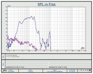
Lacking TEF measurements of a lab sub, my guess would be that the TH-118 tapped horn (now an 8 year old cabinet design) would be both more powerful and smaller. A fellow felt like you that by ignoring the constraint of package volume that a better albeit bigger subwoofer could be built with the drivers and basic alignment and he took measurements which look believable and in a way that is comparable to how the TH-118 was measured and illustrates the tapped horn’s gain when the size / low corner permits the design.
Compare the SPL (subtract 3dB for the 118 as it’s a 4 ohm box) below 100 hz, note what it is at 30, 40 , 50 Hz (these are subwoofers, both measured at 10 meters)
http://www.danleysoundlabs.com/danley/wp-content/uploads/2012/04/TH-118-spec-sheet2.pdf
Best,
Tom
Attachments
The Labhorn has a big hole right above tuning because a couple of key mistakes were made when it was folded. First, the rear chambers ended up to be significantly smaller than planned and second, the horn was designed as an end loaded horn with the first 6 (or so) inches of the horn considered part of the throat chamber. Both these mistakes contribute to the Labhorn's big gaping hole right above tuning. This is all documented in Danley's own posts while he was designing the Labhorn.
It's easy enough to get flat(ish) response from grossly undersized front loaded horns, there are lots of very petite 20 hz horns that don't have this problem.
The last paragraph (bolded) isn't correct. It isn't the lower (70 hz) hole in the FLH sim in the picture above that a tapped horn fills in, it's the higher (160 hz) hole in the BLH sim that the TH corrects with it's cleverly placed driver.
If what you say is true, then why does the graph show the opposite?

The dimensions of the horn are virtually identical, the only difference is that one is a FLH and one is a BLH. In the frequency response, we can clearly see that the BLH 'fills in' the lowest dip in the response of the FLH.
Here's my understanding of what's going on:
1) When making a horn, there is a set of parameters which are ideal. If I'm not mistaken, the formula originates from Leach and is the basis for tools like the Eazy Horn spreadsheet.
2) These 'ideals' often yield very large cabinets
3) You can use the same *length* for the horn, but reduce the *volume* of the horn, but this creates ripples in the response. These ripples get more severe as you go lower in frequency. IE, the ripples may be as little as one decibel at the top end of the response, but at the bottom end, they can be as deep as 5-10dB.

Here's a Fitzmaurice Titan 48. Note the dips at 80hz and 40hz.

Here's one of Waynes horn subs. Note the dip at 40hz.
OK, here's the most critical piece, as I understand it. (And I'm not saying I'm right, I'm just trying to articulate how I believe these work.) We can see that there are dips in the response of the FLH. But if we added another speaker to the mix, 180 degrees out of phase, there would be peaks at the same frequencies where the dips are. And that's what's happening in tapped horns and back loaded horns. For instance, if the Titan 48 was built as a BLH, the energy from the opposite side of the cone would tend to 'fill in' the dip at 40hz.
Of course there's no free lunch. BLHs and tapped horns have a couple of features that FLHs don't. The first is a dramatic increase in excursion below the tuning. Basically the driver unloads below the lowest tuning. The second feature is a deep notch in the frequency response at 3x the tuning.
Here's Tom describing it better than I can, highlighting by me:
The “Tapped horn” came to life when I was thinking about the reflection that occurs when the sound from the drivers in fig#2 bounces back from the closed end and causes a cancellation notch.
That notch defines (just above) the upper limit of the usable response for the drivers in that position.
I wondered what happens “IF” I substituted an active source instead of a reflection and inverted the source to add instead of cancel similar to a transmission line..

Here's a measurement of a Bassmaxx sub.
See how the response in it's passband is smoother than many front loaded horns?
And see how there's a dip at 175hz? If I'm not mistaken, that dip indicates that the Bassmaxx is tuned to something around 52hz.
There's another factor that has to be considered too. Modern drivers typically have much higher QTS. Twenty years ago there were tons of drivers with a QTS of under 0.30. Nowadays, that's uncommon. Twenty years ago there weren't a lot of subwoofers with QTS of over 0.50; nowadays there's hundreds. Of course this isn't accidental; as amplifiers have become bigger and cheaper than ever, loudspeaker manufacturers have responded by making drivers with cones manufactured out of aluminum or composite, and with xmax specs that are dramatically higher. But all of that adds weight, and the higher moving mass increases the QTS.
An example of this is the Alpine Type R and the MCM 55-2421. The latter is an old school design, with a paper cone and high BL. The former is a new school design, with a composite cone and lower BL. On paper, the MCM looks like a better horn driver. But drop that Alpine into a tapped horn and the improvement in sound quality is unmistakable. Basically the high QTS of the Alpine makes it a dubious candidate for a small FLH, but in a TH or BLH we can flatten out the dips, and the Alpine's strong cone and low distortion make it sound more "hifi".
... how much does a 20% change in back volume cause?
Let's start with a simulation of the original design (before folding). The details of the original design (after chopping it up into separate cabs) is as follows:
St = throat area = 80 sq ins (40 sq inches per driver)
Vb = rear chamber volume = 1530 cu in per driver (separate rear volumes for
each driver)
Vf = front chamber volume = 170 cu in per driver (volume between cone & throat)
Flare = 26.4 Hz, hyperbolic t = .5, path length = 126 inches (inc front volume)
... and yields this response.
An externally hosted image should be here but it was not working when we last tested it.
I think we can all agree that there is no big gaping hole in response right above tuning in the original (unfolded) design.
(Note that this is not entirely accurate, since the first 6 (or so) inches of the horn are included both in the front chamber volume AND in the horn flare, I just input everything exactly as specified and didn't bother to do the math to find out how much smaller the front chamber should be when simulated properly.)
Acoustically the “saddle” in a bass horns response reflects the mouth being too small ...
The saddle CAN be caused by an undersized mouth, but the simulation above shows that this is not the case with the original (unfolded) Labhorn design. There is no saddle.
Now let's go ahead and explore the implications of making the rear chambers 20 percent smaller and simulating as an end loaded horn but folding as an offset driver horn.
I'm going to switch now to an approximation of the folded Labhorn (not accurate but close enough) to explore these effects for a couple of reasons. First, the Labhorn changed considerably during folding (it lost about 100 liters) and second, because I can't sim an offset driver horn with a hyp-ex flare.
An externally hosted image should be here but it was not working when we last tested it.
This graph shows an approximation of the Labhorn (still end loaded) with a full sized rear chamber (as per the original plans) in dark black vs a chamber that's 20 percent too small in light grey. You have to look close to see the effect. The reduced chamber size makes the peak at tuning a bit bigger and creates a small saddle right above tuning. This by itself is not catastrophic but now let's explore the effect of simulating as an end loaded driver but folding as an offset driver horn.
An externally hosted image should be here but it was not working when we last tested it.
This is with the full sized rear chamber in dark black vs offset 32 cm in light grey. It's offset too far since I don't have enough segments available in Hornresp to put it where it should be, so again not accurate but good enough to see the effect. Again you have to look close to see the effect, but this also creates a bit of a saddle.
Now one last sim to show BOTH the effect of an undersized rear chamber AND the effect of simulating end loaded but folding offset.
An externally hosted image should be here but it was not working when we last tested it.
So that's the end loaded Lab with a full sized rear chamber in dark black vs the offset driver with 20 percent undersized rear chamber in light grey. You don't have to look so close anymore to see things are getting quite a bit different than the original design.
The Labhorn's saddle has nothing to do with an undersized mouth, the fold simply just does not match the original design.
This post is getting too long already, I'll address some of the other points in my next post.
Before I start, let me say I'm a huge fan of you and your work. I'm not trying to be overly critical here, just pointing out the reason for the Labhorn's saddle.
I didn't receive any PM or email.
The Labhorn design posts paint a pretty clear picture of your thoughts during the design. It's a great design but it lost a lot of it's magic when it was folded.
I was under the impression that you did use Akabak for this design but if not it's very impressive despite it's faults.
I can beat it by a couple of db on paper but in real life the extra compression ratio and power compression might make those gains disappear in short order. Again, the Labhorn design is impressive, the fold is not.
A properly designed and folded flh won't have the saddle. And while it is true that the tapped horn doesn't have the saddle problem it's due to a completely different impedance curve. The saddle (when present) is due to having the impedance peaks too far apart.
Hi
If you have the posts handy, that would be cool, I will send you a message with my home e-mail.
I didn't receive any PM or email.
If you want to get a better feel for how this project evolved (looks like I designed it at the end of 2001 so 13 years ago), consider what could be done without using McBean’s or Akabak like the lab sub was. Also keep in mind, my sketches were what I based the numbers on, there was no cad until the layout was done and sent off and how much does a 20% change in back volume cause?
The Labhorn design posts paint a pretty clear picture of your thoughts during the design. It's a great design but it lost a lot of it's magic when it was folded.
I was under the impression that you did use Akabak for this design but if not it's very impressive despite it's faults.
What you might do for fun is see if by keeping the same outside dimensions and the low cutoff the group wanted for a group of 6, how much better one could do with modern design tools and cad.
I can beat it by a couple of db on paper but in real life the extra compression ratio and power compression might make those gains disappear in short order. Again, the Labhorn design is impressive, the fold is not.
Acoustically the “saddle” in a bass horns response reflects the mouth being too small and while the resonant behavior is ideally masked by resistance at both ends, it isn’t once the horn mouth is too small. The tapped horn canfill in that large saddle between the first and second peaks.
A properly designed and folded flh won't have the saddle. And while it is true that the tapped horn doesn't have the saddle problem it's due to a completely different impedance curve. The saddle (when present) is due to having the impedance peaks too far apart.
If what you say is true, then why does the graph show the opposite?
The graph doesn't show the opposite. What it does show is a terrible front loaded horn design.
A properly designed and folded front loaded horn won't have a saddle. At worst it will have a very small saddle. There are several grossly undersized front loaded horns that don't have that saddle. Lilmike makes them all the time, low tuned acoustically tiny horns with no saddle. The unfolded Labhorn design has no saddle either.
The key to getting rid of the saddle is to make the front chamber larger or to change the flare to move the impedance peaks closer together, or a combination of both. The former will mess up your reactance annulling (if it was reactance annulled in the first place) and reduce xmax limited max spl, the latter doesn't really have any consequences if the design is viable in the first place and if you only make the changes that need to be made to remove the saddle.
The tapped horn was not invented to remove this saddle right above tuning. It's a completely different alignment than a flh. The tapped horn is simply a back loaded horn with the driver placed to remove the first big dip caused by the BLH's natural resonances. A properly designed BLH won't have the saddle right above tuning but it WILL have a deep notch higher up in frequency. THIS is what the tapped horn fills in.
Last edited:
Wayne's 12Pi addressed the front and back chamber issues and made the cabinet larger than Tom's Labhorn, it still has a saddle.The key to getting rid of the saddle is to make the front chamber larger or to change the flare to move the impedance peaks closer together, or a combination of both.
The tapped horn was not invented to remove this saddle right above tuning. It's a completely different alignment than a flh. The tapped horn is simply a back loaded horn with the driver placed to remove the first big dip caused by the BLH's natural resonances. A properly designed BLH won't have the saddle right above tuning but it WILL have a deep notch higher up in frequency. THIS is what the tapped horn fills in.
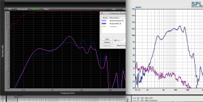
You can see another saddle example below, a pair of Lab 12 compared to a BC18SW115 in the same tapped horn cabinet.
Art
Attachments
Wayne's 12Pi addressed the front and back chamber issues and made the cabinet larger than Tom's Labhorn, it still has a saddle.
You can see another saddle example below, a pair of Lab 12 compared to a BC18SW115 in the same tapped horn cabinet.
Art
How big is the reach chamber in the 12pi? I can find no reference.
Edit, I see the initial sims say 50 liters (dunno if this is before or after driver displacement). the dips are not reflected in the sim though.
Last edited:
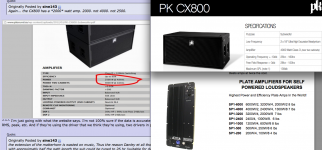
The CX800 uses one amp to power two cabinets.Again... the CX800 has a *2000* watt amp. 2000. not 4000. not 2500.
The amp is likely the DSP version of the Speakerpower SP4001.
The SP4001 puts out 4000 watts in to 2 ohms (two cabinets) or 2500 in to one 4 ohm cabinet.
The SP4001 is rated at 2400 watts at 4 ohms, but the PK actual load is probably a bit under 4 ohms, so 2500 watts is not a stretch.
The SP4001 handles two ohm loads with no thermal problems.
As you have reported EDM music with less than 3 dB crest factor, 1000 watts per cone is about all the average power the speakers in the PK CX800 could handle with that kind of crest factor.
Properly managed, with separate peak and RMS limiters, the speakers could safely handle 2 or 3 times that power, but considering PK is carving it's niche in genres with limited dynamic range, the added expense of more power probably wouldn't be warranted.
As far as any debate over horn vs vented box, the vented box wins by a bit from an output per transport size standpoint, but TH or FLH win from an output per driver and watt.
Considering the horn option can cut the amount of drivers in half, and power by 1/4, from a cost standpoint when transport is not figured in, horns are a big win.
And of course, Hoffman's iron law comes in to play, low, loud or small- pick two.
When comparing two cabinet types, if the low frequency response extension is not the same, the comparison is not valid.
Art
Attachments
Wayne's 12Pi addressed the front and back chamber issues and made the cabinet larger than Tom's Labhorn, it still has a saddle.
I don't know the details of the 12Pi but as I've clearly shown it doesn't need to have a saddle. As long as you simulate a good design and accurately build what you simulated there's no reason for this saddle.
There's always going to be a bit of a dip between the impedance peaks especially in grossly undersized front loaded horns but it doesn't have to be a big dip. Here's the simulated and measured response of Lilmike's F20 front loaded horn. At about 450 liters it's GROSSLY undersized compared to the tuning frequency. It's got a bit of a dip, you could even call it a saddle, but it's not even as deep as the Labhorn's saddle.

You can see another saddle example below, a pair of Lab 12 compared to a BC18SW115 in the same tapped horn cabinet.
Art
That dip could be fixed right up by altering the flare or dropping in another driver (like a BC18SW115 maybe).
The point here is that you can have a saddle if you want one (although I'm not sure why you would want one) but you absolutely don't need to have one. A mild dip is always preferable (IMO) and always achievable.
The CX800 uses one amp to power two cabinets.
The amp is likely the DSP version of the Speakerpower SP4001.
The SP4001 puts out 4000 watts in to 2 ohms (two cabinets) or 2500 in to one 4 ohm cabinet.
The SP4001 is rated at 2400 watts at 4 ohms, but the PK actual load is probably a bit under 4 ohms, so 2500 watts is not a stretch.
The SP4001 handles two ohm loads with no thermal problems.
As you have reported EDM music with less than 3 dB crest factor, 1000 watts per cone is about all the average power the speakers in the PK CX800 could handle with that kind of crest factor.
Properly managed, with separate peak and RMS limiters, the speakers could safely handle 2 or 3 times that power, but considering PK is carving it's niche in genres with limited dynamic range, the added expense of more power probably wouldn't be warranted.
As far as any debate over horn vs vented box, the vented box wins by a bit from an output per transport size standpoint, but TH or FLH win from an output per driver and watt.
Considering the horn option can cut the amount of drivers in half, and power by 1/4, from a cost standpoint when transport is not figured in, horns are a big win.
And of course, Hoffman's iron law comes in to play, low, loud or small- pick two.
When comparing two cabinet types, if the low frequency response extension is not the same, the comparison is not valid.
Art
I too initially thought that the amps were the speakerpower SP4001. Reportedly they are Powersoft plate amps however. In the 8 times I've experienced large stacks of PK Sound amps, it was clear that they did indeed use 1 powered sub to power itself and 1 passive sub (Every Time). One of these situations (artists Datsik, 8x cx800s) I was actually standing between the substack and the stage, and saw this to be the case (and unfortunatly neglected to take pictures).
All the other shows used stacks of 24 or more PK subs ( sub 2k person) , so they were coasting (amp size irrelevant).
9k a piece (used) has been tossed around for the cx800.
danley also talked about making matterhorns tuned higher (in the 20 to 25 range) which would be more sensitive (more output).
Just for the lulz, here's what a "mini-matterhorn" might look like if it was a FLH instead of a tapped horn.
I think a FLH is compelling for a couple reasons:
1) The MTX 9515 has a low FS, and due to that, it likes a tapped horn that's tuned low... Trying to put the 9515 into a short tapped horn is like trying to put the 9515 into a vented box that's tuned too high.
2) Can you *imagine* what the impact of forty of these would have? Would be like getting punched in the chest.

^^ Here's the response graph. Matterhorn at 40,000 watts, Mini-Matterhorn at 60,000 watts.

That 9515 is a BEAST. 60,000 watts and it's not exceeding xmax at any frequency.

Impedance of the two.
The "mini-matterhorn" is 2/3rds the size of the Matterhorn sim I posted, at 477 cubic feet.
An externally hosted image should be here but it was not working when we last tested it.
You could likely get it into one of these 8x10 containers.
If anyone is zany enough to build this, I noticed that the MTX subs are back in stock again 🙂 🙂
https://www.mtx.com/t9515-44-mtx-car-subwoofer
I too initially thought that the amps were the speakerpower SP4001. Reportedly they are Powersoft plate amps however. In the 8 times I've experienced large stacks of PK Sound amps, it was clear that they did indeed use 1 powered sub to power itself and 1 passive sub (Every Time). One of these situations (artists Datsik, 8x cx800s) I was actually standing between the substack and the stage, and saw this to be the case (and unfortunatly neglected to take pictures).
All the other shows used stacks of 24 or more PK subs ( sub 2k person) , so they were coasting (amp size irrelevant).
I went to see Datsik here in San Diego and he played on the club's crappy system, it was l-a-m-e.
Excision is playing the Shrine in LA next month, hopefully he brings the bass.
If you know of any other huge systems that are touring, let me know, I will totally go to a show just to hear a monster setup
I just saw Bassnectar/Datsik/pretty lights 2 days in a row on 42 meyer hp 700s at basslights last month. Free tickets so I couldnt turn em down even though I stopped being into the whole bro thing in 2011
Oh and Art, I'm pretty sure that Hunter pegged to the max can still burn up a pk sub even with only 1000 watts acone (34hz tuning equals excursion and impedence minima righhhht where hunter rolls for 5 minutes flat).
Oh and Art, I'm pretty sure that Hunter pegged to the max can still burn up a pk sub even with only 1000 watts acone (34hz tuning equals excursion and impedence minima righhhht where hunter rolls for 5 minutes flat).
Last edited:
The 12Pi Hornresp sim does not show a saddle, but as built it does, with the average measured frequency response fairly close to the sim.As long as you simulate a good design and accurately build what you simulated there's no reason for this saddle.
Here's the simulated and measured response of Lilmike's F20 front loaded horn. At about 450 liters it's GROSSLY undersized compared to the tuning frequency. It's got a bit of a dip, you could even call it a saddle, but it's not even as deep as the Labhorn's saddle.
Lilmike's sims shows more of a saddle than as built, and comes in 5 Hz higher (1/3 octave!) than the sim (within 1Hz of the driver's FS).
So which is more accurately built 🙄?
I just saw Bassnectar/Datsik/pretty lights 2 days in a row on 42 meyer hp 700s at basslights last month. Free tickets so I couldnt turn em down even though I stopped being into the whole bro thing in 2011
I nearly flew out to that show! Ended up going to Texas instead. Nearly went to Lights All Night but ended up skipping it.
Saw Bassnectar in Vancouver in '12, Datsik in San Diego in '13, and Pretty Lights at 'Lucky' in Seattle in '12.
I too initially thought that the amps were the speakerpower SP4001. Reportedly they are Powersoft plate amps however. In
It's possible that the answer is "both."
I noticed on their FB page that they were posting pictures from Italy, and mentioned they were there for business. So perhaps the cabinets were once powered by Speakerpower, and are now powered by Powersoft.
- Home
- Loudspeakers
- Subwoofers
- Old School Horn vs Modern Vented Box