poobah said:I have been intrigued by that toner tranfer thing also. At worst, it could serve as base that you could recoat or touch up with a pen.
🙂
Yes, actually the drum of my laser printer is getting old. I don't see any problems in what I usually print out, but it does cause some problems that need touching up when used for this. I use acrylic paint for touch up, but that is mostly because I paint and have a lot of it anyway. It is good though, since it is thich, and covers and sticks well.
Hi Christer,
I did pick up some "Avery Iron-On Transfers" P/N 04384. I could not find stock on any that were mentioned in the thread. I'll locate it and read it again.
Hi poobah,
Man, I would just love to print and go. I tried filling in, but some of the fine detail just becomes a mess. I would like to use some of the newer smt parts.
-Chris
anatech said:Hi Christer,
I did pick up some "Avery Iron-On Transfers" P/N 04384. I could not find stock on any that were mentioned in the thread. I'll locate it and read it again.
Are they supposed to be used with laser printers, or is it one of those T-shirt transfer kits for ink jets? Maybe the latter works too. I don't know.
Hi Christer,
These are intended for ink jet printers. I could find nothing for laser printers at the time.
I chickened out running these through my old workhorse. I felt it deserved a better death than that.
-Chris
These are intended for ink jet printers. I could find nothing for laser printers at the time.
I chickened out running these through my old workhorse. I felt it deserved a better death than that.
-Chris
anatech said:Hi Christer,
These are intended for ink jet printers. I could find nothing for laser printers at the time.
I chickened out running these through my old workhorse. I felt it deserved a better death than that.
-Chris
But the point is to use ordinary photo paper, intended for photo quality prints with ink jet printers, but use it in the laser printer instead. It is no special kind of paper inteded for transfers at all, just photo paper that you misuse in this way. The problem is to find a photo paper that works well when misused. 🙂
I tried Kodak and TDK photo papers, but were not satisfied with the results. Then I tried a cheaper paper that worked well. Still takes some experimentation to get it right. Try the print and transfer process a copuple of times without etching the board, just scrubbing off the transferred pattern inbetween, until you feel you get it right.
Several people have described the method, both here and elsewehere. Here is a short tutorial I posted a few years ago:
http://www.diyaudio.com/forums/showthread.php?s=&threadid=34752&highlight=
(Sorry for the bad picutures, I only had a very simple and bad digital camera at the time).
PCB transfer
Well, since my original idea is not going to be pursued any longer (I thank everyone who made post in regards to the old method), I will give my input on the toner transfer method. I have been using alot lately and it always works. But I use the Techniks blue paper, and it never fails. It always peels away nicely, I recommend it. I have tried paper, but the paper I was using did not peel off too well. Anyway, it's the way to go!
The only reason I wanted to know more about the old methods of Printed circuits was because I wanted to produce pcbs that had a classic seventies look to them, made with the same painstaking method that was used. Maybe I'm too picky, but I like old things. I love the new method alot more because it's much more efficient! All you need is the blue paper and a laser printer, cheers
The question is if you will see much difference on the final result? A home made PCB today will look pretty much like they did in the 70's.
Whether you use toner transfer, photographic transfer or tape and precut pads, the final result will be hard or impossible to distinguish from each other. The etchants and board materials are more or less the same too.
Whether you use toner transfer, photographic transfer or tape and precut pads, the final result will be hard or impossible to distinguish from each other. The etchants and board materials are more or less the same too.
Christer,
What makes a board look 70's is the curved and often crooked traces that were laid by hand.
🙂
What makes a board look 70's is the curved and often crooked traces that were laid by hand.
🙂
poobah said:Christer,
What makes a board look 70's is the curved and often crooked traces that were laid by hand.
🙂
Yes, but nobody suggested he must use a CAD system to do them.
Draw by hand on paper, scan and use transfer method of choice. Shouldn't look different, I guess.
wow...
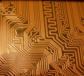
I wonder if that is to equalize propogation delays?
There are other reasons for doing that though.
😕
I wonder if that is to equalize propogation delays?
There are other reasons for doing that though.
😕
poobah said:wow...
I wonder if that is to equalize propogation delays?
There are other reasons for doing that though.
😕
There's a lot of such traces, and it is never regular or systematic in any obvious way, so they must have put a lot of effort into it, I guess. I don't know why they do it. My guess is also to equalize propagation delays, or even deliberately modify it for certain signals. But I am curious about what other ideas you have? Deliberate inductance? Questionable.
I can't remember seeing anything like this on my old MB, though, but that one is over 5 years old.
Christer said:There's a lot of such traces, and it is never regular or systematic in any obvious way, so they must have put a lot of effort into it...
Probably the autorouting alogarithm just puts kinks in where it fancies to equalise path lengths.
poobah said:Christer,
What makes a board look 70's is the curved and often crooked traces that were laid by hand.
🙂
And the blood stains from the scalpel ....... BTDT etc etc
pinkmouse said:
Probably the autorouting alogarithm just puts kinks in where it fancies to equalise path lengths.
Yes, maybe autorouters can do this if one asks them to have equal path length. It wouldn't be that difficult, of course, to write an algorithm that inserts serpentines wherever there is place for them if a longer trace is needed. It might have to move things around and try a couple of times though. What made me suspect human interaction is that these serpentines ought to add inductance, but I realize now i was thinking wrong. The way they are laid out will rather cancel the fields to minimize inductance.
Christer said:
Yes, maybe autorouters can do this if one asks them to have equal path length. It wouldn't be that difficult, of course, to write an algorithm that inserts serpentines wherever there is place for them if a longer trace is needed. It might have to move things around and try a couple of times though. What made me suspect human interaction is that these serpentines ought to add inductance, but I realize now i was thinking wrong. The way they are laid out will rather cancel the fields to minimize inductance.
That is now standard fare on modern autorouters: Routed pathlength is one of the database parameters and can be set to equal another path or to a specified length (=delay).
Rip up and retry will also push other stuff out of the way to achieve this.
Very common now on PC boards when one is chasing pSecs.
anatech said:Hi Christer,
These are intended for ink jet printers. I could find nothing for laser printers at the time.
I chickened out running these through my old workhorse. I felt it deserved a better death than that.
-Chris
Good thing that you chickened out. These iron-on transfers would have destroyed your laser printer.
The layer that is supposed to be ironed on the t-shirt, is melting at quite low temperatures, wich would have made your drum a little "sticky" 😀
Please use them for t-shirts only 😉
best regards
Ebbe
cliff said:
Very common now on PC boards when one is chasing pSecs.
Yes, I suppose all modern motherboards look like that now. The clockspeeds are crazy high nowadays.
Hi Ebbe,
These are neat though. They are 4" X 6". Great size for small boards with minimum waste.
-Chris
Actually, it's the fuser assembly that would become a sticky mess. They are intended for ink jets. I think I'll buy an inkjet on sale for this to try.wich would have made your drum a little "sticky"
These are neat though. They are 4" X 6". Great size for small boards with minimum waste.
-Chris
- Status
- Not open for further replies.
- Home
- Design & Build
- Parts
- old pcb method, vintage pcb, fr4, bakelite