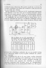
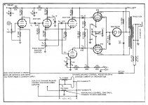
While browsing through some old Audio magazines I came across this article for an amplifier which uses a three triode phase inverter. Since I like the Van Scoyoc cross coupled inverter, this one stood out. The author has a patent on it (below), but uses a modified version. Here's the article. Thought someone might be interested.
I also saw an amp that uses this version but with type EFP60 secondary emission tubes. I have some of those but no sockets. They're a strange looking loctal style but with 9 pins.
I also saw an amp that uses this version but with type EFP60 secondary emission tubes. I have some of those but no sockets. They're a strange looking loctal style but with 9 pins.
Attachments

It would be interesting to compare that to the analogous circuit that would be three 6SN7 halves setup as a grounded cathode amp driving a LTP phase inverter.
EFP60
EFP60, not a power tube but developed for TV IF has a very large gain/bandwidth product. So it is able to provide a very low drive point impedance (16K) in this cct to the following grid. And still provide sufficient gain. In an RC coupled cct this results in lower distortion.
Used lots of them when they were available but never in an audio amp.
They are a 9-pin Loctal. Ours were from Philips. Pulses into 50R circuits had risetimes of a very few nanoS.
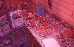
Those red things on my test bench are EFP60s. I was involved in some research on magnetic core memory systems. By the scopes you can see it is circa 1960.🙂
EFP60, not a power tube but developed for TV IF has a very large gain/bandwidth product. So it is able to provide a very low drive point impedance (16K) in this cct to the following grid. And still provide sufficient gain. In an RC coupled cct this results in lower distortion.
Used lots of them when they were available but never in an audio amp.
They are a 9-pin Loctal. Ours were from Philips. Pulses into 50R circuits had risetimes of a very few nanoS.
Those red things on my test bench are EFP60s. I was involved in some research on magnetic core memory systems. By the scopes you can see it is circa 1960.🙂
Attachments
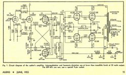
....The author has a patent on it.....
So?
You can build one "for study". Philosophically, as a stepping-stone to your own wonderful improvements in the art. In practice, if you don't go whoring your copy all over town, nobody cares.
Anyway: "HAD" a patent. They expire. 17 years, 20 years, the laws vary and do change.... but a 1952 patent is long-gone.
Looks wonky to me. And I've had enough wonky splitters. But go ahead and find something wonderful about this one.
Yes PRR, I know this. I mentioned it to post it for those curious. I can list probably six different inverter types and they all work. And it really comes down to what the designer thinks/likes best since they all have pros and cons.
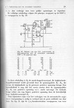
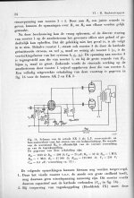
Some other examples of (more or less) unusual phase inverters:
1) A single EEP1 (a secondary emission tube similar to the EFP60 but with a side contact or P-base).
2) An EK2 (octode).
3) An ECH21 (triode-heptode).
Source: Book V from the Philips series on Electron Tubes (1951)
1) A single EEP1 (a secondary emission tube similar to the EFP60 but with a side contact or P-base).
2) An EK2 (octode).
3) An ECH21 (triode-heptode).
Source: Book V from the Philips series on Electron Tubes (1951)
Attachments
Last edited:
Some other examples of (more or less) unusual phase inverters:
1) A single EEP1 (a secondary emission tube similar to the EFP60 but with a side contact or P-base).
2) An EK2 (octode).
3) An ECH21 (triode-heptode).
Source: Book V from the Philips series on Electron Tubes (1951)
Are those books available somewhere as a (scanned)copy on the internet?
Yes, they are here:
electron Tube Data sheets - PHILIPS' TECHNICAL LIBRARY - Series on ELECTRONIC TUBES
I scanned books IIIb and V, and found book X, and mailed them to Frank. Recently I also found books VIIIa and VIIIb (in English) and also mailed them to Frank, but he did not put them on his site yet. I have searched for Book VI but no library in The Netherlands knows of this book so the conslusion that it was never published seems correct.
Last edited:
I don't know why can't the second triode's cathode be direct coupled to the phase inverter by removing C3 and increasing PI's cathode resistor, like below, so both phases draws same amount of current.
I would still prefer the Williamson circuit but at least this phase inverter allows direct coupling to the drivers and both sides travel through the same number of stages, unlike a paraphase circuit.
I would still prefer the Williamson circuit but at least this phase inverter allows direct coupling to the drivers and both sides travel through the same number of stages, unlike a paraphase circuit.
Attachments
Hi, may I ask why the screens of the scopes were "covered" by that "periscope-like" thing?By the scopes you can see it is circa 1960.🙂
Hi, may I ask why the screens of the scopes were "covered" by that "periscope-like" thing?
Maybe I can answer this : We used that kind of thing to look for some spike or oscillation on a signal which
otherwise could not be noticed due to the environmental (laboratory) light. Yes, you could increase the
beam intensity but then most of the time the signal more or less blurred.
Yes, they are here:
electron Tube Data sheets - PHILIPS' TECHNICAL LIBRARY - Series on ELECTRONIC TUBES
I scanned books IIIb and V, and found book X, and mailed them to Frank. Recently I also found books VIIIa and VIIIb (in English) and also mailed them to Frank, but he did not put them on his site yet. I have searched for Book VI but no library in The Netherlands knows of this book so the conslusion that it was never published seems correct.
Thank you very much for supplying this link!
Also will send you a PM.
Thank you very much for the explanation Joe, a smart solution to overcome technology limits, indeed.Maybe I can answer this : We used that kind of thing to look for some spike or oscillation on a signal which
otherwise could not be noticed due to the environmental (laboratory) light. Yes, you could increase the
beam intensity but then most of the time the signal more or less blurred.
It's likely not desirable to have different operating points and load resistors for that last pair of triodes, hence the cap coupling used there to keep the bias voltages and plate currents approximately the same.I don't know why can't the second triode's cathode be direct coupled to the phase inverter by removing C3 and increasing PI's cathode resistor, like below, so both phases draws same amount of current.
Hi, may I ask why the screens of the scopes were "covered" by that "periscope-like" thing?
Much of the work could be done with pulse generators based on the EFP60 & 6DQ5. EFP60 was good for about 0.25 Amp. The 6DQ5 when pushed hard would drive 1.5 Amps into a 50R transmission line. All the test signals are in 50R.
But there were times when we needed even shorter rise times & large pulses, difficult with the technology of the time. One way out is the charged transmission line discharged by a mercury relay. But in that case the rep rate is low so the display is not bright at all.
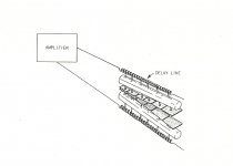
Another problem, we were bandwidth limited by the scopes. The TEK 540 series had a RT of about 10 nS / 30 MHz. We needed something better, it turns out that some TEK scopes of the time allowed direct access to the vertical plates of the CRT. So we ran 50R transmission line in thru that port. But that avoids the scope delay line so can't see the leading edge of a step function. An external delay line, a length of COAX is the cure.
One solution to the BW limitation is the distributed amplifier. In the HP180 series scopes a delay line is built into the CRT to improve defection limitations. There were several vertical plate groups. In the HP140 Series the vertical amplifier is a pair of 7788s, 50 mA/V of Gm.
TEK had an external delay line as a product, it looked like a large blue traveling case so our lab bought one. They also had a camera that could be attached to the CRT face. The working part was based on the Polaroid camera. We used ASA 10000 film. Later we got one of the first TEK Sampling Scope plug-Ins. The lab also bought a TEK 540 with a superfast phosphor, don't recall the P number offhand. It was difficult to use as an ordinary scope, there was no afterglow with that phosphor.
U of Toronto Physics, a great place to work as I interned toward the P.Eng.
No audio here for this thread.😱 But along the way I built several audio amps on the side.🙂
The Tektronix 580 series were the first CRTs to incorporate the built in delay lines with segmented plates. (I still have a 585A) And I think the phosphor you refer to was the P11. A bright blue that was hard on the eyes but very good for capturing photographs.In the HP180 series scopes a delay line is built into the CRT to improve defection limitations. There were several vertical plate groups.
.
Attachments
It's likely not desirable to have different operating points and load resistors for that last pair of triodes, hence the cap coupling used there to keep the bias voltages and plate currents approximately the same.
That's EXACTLY why the driver triodes need to be direct coupled so they both have similar plate voltage and current almost like a long tail pair but separate cathode resistors. (Notice in my modded drawing the PI cathode resistor value is doubled of the driver and cathode follower.) But the author did not do that and yet in the article's simplified diagram it shows direct coupling of both triodes.
Speaking of direct coupling, it is conceivable to have the input AND driver stages be direct coupled like a Mullard circuit but with an extra cathode follower. It's a fun circuit that allows for various permutations. But what is attractive about the circuit for me, as the author stated, is the same number of tube stages that BOTH phases go through, they have the same exit time, which is something I thought only possible with the Cathodyne/Concertina/Split-Load circuit or a transformer.
When I was with HP most scopes were sold with the P31 phosphor, at TEK & Philips the same thing. But until storage scopes appeared P2 & P7 were popular for those doing work at lower frequencies. Even after storage, P2 & P7 filled many applications & saved the customer many $$$. Those phosphors were were very good for audio work.🙂
I gave away my 2-channel, 100 MHz R&S scope several years ago. They were made by Panasonic & private branded, a practice common even in hitech. At HP I sold several HP products for use in customer equipment, complete with their name on the front panel. Some HP Ink Jet printers circa 1985 are made by others.🙂 The original HP pocket calculators were made in the US ( sn has 'A' in the center) & Singapore ( sn has 'S' in the center).
My HP67 was made in Singapore.🙂
The TEK 540 series did use a distributed amplifier, from memory it was a PP 6-stage thing, so a dozen 6DK6s with four transmission lines. Impossible to adjust outside TEK. The 6DK6 was developed with computer logic in mind, the cathodes are designed to avoid 'cathode interface'.
These oddball type of phase inverters, you have to wonder, if they're "so good", how come they were never adopted by large manufacturers?
A simple cathodyne seemed to dominate the Fishers, Scotts, etc.
A simple cathodyne seemed to dominate the Fishers, Scotts, etc.
- Home
- Amplifiers
- Tubes / Valves
- Old Odd But Interesting Phase Inverter Circuit