Well WOT, you should know the answer to that. Cost, cost and cost. Another tube, socket, wiring and more chassis work. These odd PIs are from designers and DIY articles of years past. Neither I nor anyone else are claiming they were better then today's popular LTP and cathodyne. They aren't. They're just different and interesting.
I tend to agree, yes.
Just like current times, and on here...
Oddball designs, various forms of complexity, etc.
Nevertheless, keeping things relatively simple is more my speed, and using time-honored designs that worked, and worked well.
Those that insist on 0.0000000000012 percent distortion figures and obsess over anything less, or worry about inaudible hum levels, etc, are free to dig in and play.
These oddball type of phase inverters, you have to wonder, if they're "so good", how come they were never adopted by large manufacturers?
A simple cathodyne seemed to dominate the Fishers, Scotts, etc.
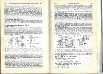
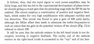
Who said that they were "so good"? And some of them did find their way into commercial products. Note the advantage of using an EEP1. It has so much gain that further preamplification (even for microphone) was not necessary.
Philips hardly used the cathodyne at first because they did not realy have a suitable tube for it. That changed with the introduction in 1948 of the ECC40 with it's Vkf max. of 175 V.
Attachments
Last edited:
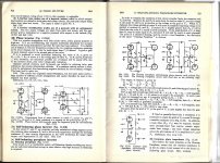
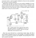
An other oddball phase-splitter from Philips (source: Hi-Fi Amplifier Circuits, Philips, 1965):
Attachments

The Europeans were known to "go overboard" on some of their designs, far back into the 50's.
For instance, the Germans, among others, used highly complex tone-shaping in their radios.
Grundig, Saba, Blaupunct, Normende, Telefunken, etc., had multiple push buttons, along with rotary bass/treble controls.
You had a choice of jazz, orchestra, soft, mellow, hifi, etc., which "contoured" the sound to your liking.
If you investigate the circuits used, it was a complicated mix of passive and active/feedback style frequency controls, boggling your mind.
I might add, multiple speakers were part of this feature, with primitive electrostatic tweeters fed from the B+/output tubes included.
These came after the 1930's/1040s American Zenith console radios that used a "Radiorgan" set of pushbuttons for tone shaping. (voice-normal-treble-alto-bass-lo bass)
I suppose the European sets were attempting to mimic the American style back then.
A selling feature of sorts, gimmicks sold sets, still do.
People, please look at page 69 former DIY member PCL200 posted!An other oddball phase-splitter from Philips (source: Hi-Fi Amplifier Circuits, Philips, 1965):
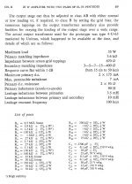
This is how a OPT specification should look like!
Last edited:
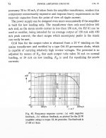
Run a simulation of post #23 Philips 10W PP amp, modified for 12AT7 and 6BQ5, and it seems to me a very good circuit.
Run a simulation of post #23 Philips 10W PP amp, modified for 12AT7 and 6BQ5, and it seems to me a very good circuit.
The Philips designers made ALWAYS good designs ! 🙂
Un-common splitters of high performance and simplicity:
The usual LTP splitter gives a pretty good low distortion performance for low level signal input, but could be further improvable with just some resistors for large input signals. The tail forces accurate complementary outputs, but unfortunately does not fix the non-linear transfer function from grid to plate for the single driven tube. Small signal span is what saves this splitter in practice.
If -both- sides of the LTP were driven, then the individual grid to plate transfer curvatures would cancel, as in a class A P-P stage. So use two resistors to cross-couple the sides (plate to grid, optional caps for DC isolation) as if building an oscillator, but keep the coupling factor just safely below the threshold for oscillation. A second set of lower value resistors goes from the grids to a negative bias V, to perform feedback signal attenuation and DC biasing.
Now the stage will automatically operate with balanced inputs and balanced outputs for low dist. splitting. (can analyze the performance by assuming accurate outputs, which then produce accurate inputs, with just a "tickle" of signal input setting the tilt or split; the positive feedbacks adjust the inputs to conform with the input signal ) The cross-coupling makes the grids conform to the input signal, so they actually raise back to Hi Z inputs.
---------------------------------------
One can do the same thing using a Beam Deflection tube, like the 6JH8. The deflectors are the differential "grid" inputs (DC levels at 0 V). So set them up the same way with cross-coupled R feedbacks from the plates to deflectors (with R-divider resistors to some neg. bias V to get 0V DC on the deflectors), with a little below unity gain. A "tickle" of signal input then sets the instantaneous tilt or split. The bottom grid of the 6JH8 sets the "tail" current (a built in CCS tail !). Unfortunately, the gain of the 6JH8 at the plates is low (Mu around 6), small Mosfet cascodes (grounded gate) can be put above the plates to increase the gain significantly.
(6ME8 can operate with the deflectors at +75V, but it is not as linear as the 6JH8 over as large an input signal range.)
Last edited:
For the above cross-coupled balanced LTP splitters, there is a subtlety in the operation.
A conventional LTP (say CCS tail) driven on one side will adjust the tail voltage to get near to half the delta grid to cathode V on both sides, so comes close to balanced drive. But the gm on each side is not equal, except in the middle, so the input signal splitting will not be as accurate as actual balanced inputs. Odd harmonic generation is the common result, especially with larger input signals. With the cross-coupled scheme, the tail voltage barely moves (only by distortion level amounts), so the complementary inputs are well maintained. In other words, the gm distortion affects the input splitting in the conventional case, but not much in the forced cross-coupled case. The CCS tail acts to vary common mode voltage to maintain constant overall current, but does nothing to guarantee linear input gm operation.
Tubes with a constantly ramping gm versus current will work best in LTP splitters of either kind, since the gm sum in class A stays the same for a constant current tail. 12AT7 is such a tube. (while 12AT7 is not particularly linear for a grounded cathode stage)
The 6JH8 beam deflection tube goes even further with first order constant gm for both deflector inputs, due to the deflection properties. One could almost leave out the cross-coupling for the beam deflection case, except single input would add a common mode signal to the inputs which would act back on the internal CCS with 3/2 power non-linearity. ( the deflectors acting like screen grids for the pentode below)
Last edited:
Very similar circuit appears in Radiotron Designer's Handbook p 527 (http://www.tubebooks.org/Books/intro_RDH4.pdf)
- Home
- Amplifiers
- Tubes / Valves
- Old Odd But Interesting Phase Inverter Circuit